
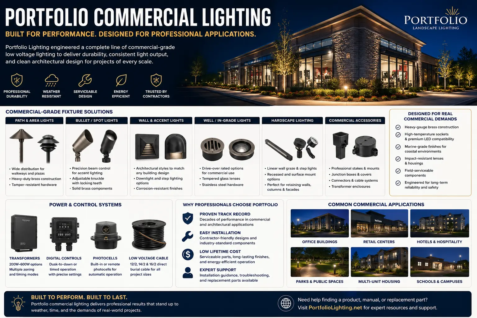
🏢 Portfolio Commercial Spec Alert: Typing the part number you found stamped on a visible downlight trim into a search engine is a guaranteed way to hit a dead end. Commercial Portfolio architectural fixtures aren't single products—they are multi-part assemblies hidden behind drywall and acoustic tile. In my 25 years tracking down components for office complexes, retail spaces, and institutional facilities, I have found that replacing the wrong part of the stack can burn out your emergency backups or trip your dimming panels. Before you order structural hardware or approve a costly lighting overhaul, use my 7-Point Architectural Framework & Driver Compatibility Blueprint right below.
My 7-Point Architectural Framework & Driver Compatibility Blueprint
To fix or replace commercial-grade Portfolio lighting, you have to treat the installation as a puzzle of four independent components rather than a simple light fixture. If you pull down a decorative reflector ring assuming it matches the rough-in frame hidden above the ceiling plane, you will end up with mismatched clips, unseated housings, or a driver that won't speak to your facility's centralized dimming network.
When I audit a commercial ceiling grid to figure out why a lighting zone went dark or started misbehaving, I map out the complete component hardware stack using these seven field rules:
- 1. Separating the Rough-In Frame from the Trim: The heavy-gauge steel frame plaster-ring is permanently mounted to your structural ceiling channels. The visible aluminum trim simply snaps into this frame using friction clips or torsion springs—meaning a number on the trim only identifies the plastic or metal cone, never the rough-in bucket.
- 2. Testing the Remotely Mounted LED Driver: When a commercial light completely drops out, the light board itself is rarely dead. The issue is almost always the electronic driver tucked inside a detached junction box above the deck; I check its milliamp (mA) output and forward voltage before searching for replacements.
- 3. Decoding Prototypical Architectural Blueprints: If you are working off a facility master schedule, the "Type L1" or "Type A3" designation you see is an independent fixture tag created by the project electrical engineer. It will never match the factory manufacturing labels pasted onto the aluminum housings.
- 4. Matching 0-10V and Line-Voltage Dimming Controls: Commercial Portfolio drivers use dedicated low-voltage purple and gray wires to handle 0-10V continuous dimming signals. If you drop in a standard residential-grade replacement driver, you will lock the fixture at 100% brightness or trigger endless flickering across the entire switch leg.
- 5. Identifying Replaceable LED Engines vs. Sealed Modules: High-end architectural units use modular LED pucks screwed onto heavy aluminum heat sinks with quick-disconnect pins. I always check if we can swap out just this internal module before condemning the entire recessed housing.
- 6. Accounting for Emergency Battery Backups: If your downlights serve as emergency egress paths, they are tied to local dual-feed battery packs or centralized inverters. Intercepting these lines with unmatched driver hardware can permanently ruin the charging circuits or compromise fire safety codes.
- 7. Navigating Discontinued Legacy Product Footprints: If your building was outfitted over a decade ago, matching the original aperture cutout diameter is your biggest challenge. Rather than patching drywall or cutting steel beams, I pivot to specialized commercial retrofit rings that adapt modern energy-efficient cores to old ceiling openings.
⚠️ CRITICAL RETROFIT RISK: Forcing an incorrect constant-current milliamp driver onto a sensitive architectural LED module, or cross-wiring your low-voltage dimming leads with 277V mains power, will instantly vaporize your lighting array and fry your facility control panels. I map out how to avoid these catastrophic circuit failures step-by-step inside our wiring schematics below.
I have built this field guide specifically for facility managers, master electricians, commercial contractors, and property owners who need to accurately identify what is sitting above the ceiling tile, diagnose the core root of a system failure, and decide whether a localized component repair or a drop-in retrofit kit is the safest and most cost-effective path forward. Scroll down to access my full step-by-step voltage calculators, ballast-to-driver conversion charts, and commercial frame measurement dimensions.
The Portfolio Commercial Product Map
Commercial lighting assemblies are easiest to understand as a stack of replaceable and non-replaceable layers. Start at the branch circuit and work downward toward the visible aperture.
1. Frame or Housing
The structural part above the ceiling. It controls aperture size, mounting method, plenum depth, thermal environment and access.
2. Junction Box
The line-voltage connection point. It may also contain emergency, dimming or control conductors.
3. Driver or Ballast
Converts branch-circuit power into the electrical output required by the lamp or LED engine.
4. LED Engine or Lamp
The actual light-producing component. It may be replaceable, proprietary or permanently integrated.
5. Reflector and Trim
Controls beam shape, glare, cut-off, finish and the visible relationship with the ceiling.
6. Control and Emergency Options
0-10V dimming, phase control, digital control, emergency battery equipment or generator transfer requirements.
Use the Portfolio Lighting catalog for broad product identification, then move to the Portfolio architectural LED catalog guide when the labels use commercial family codes rather than ordinary retail model numbers.
Seven-Point Commercial Fixture Identification Protocol
Do this before removing components, ordering drivers or approving a retrofit. One photograph from the floor is not enough.
- Photograph the visible aperture. Include the ceiling, trim shape, reflector finish, lens, wall-wash opening and any emergency indicator.
- Measure the actual ceiling cutout. Do not substitute the marketed aperture size. Record the opening in at least two directions.
- Record every accessible label. Photograph the frame, housing, trim, LED engine, driver, emergency pack and junction-box wiring diagram.
- Identify the light source architecture. Determine whether the unit uses a screw-base lamp, pin-base lamp, replaceable LED engine or sealed integrated module.
- Record electrical ratings. Capture input voltage, frequency, driver output voltage, output current, wattage, power factor and dimming method.
- Document control conductors. Purple and gray or pink low-voltage leads commonly indicate 0-10V control, but verify the actual wiring diagram before assuming.
- Inspect the ceiling environment. Note insulation contact, air-handling/plenum requirements, ceiling thickness, access limitations, sprinkler conflicts and mounting-bar condition.
If labels are incomplete, the Portfolio model-number lookup, model specifications guide and technical archive provide the best next search path.
Commercial Model-Code Decoder: What the Label Is Telling You
Commercial catalog strings combine several decisions in one line. The same family code may be followed by aperture, lumen, beam, voltage, driver, dimming, emergency, finish or distribution options.
| Code Pattern Seen on Portfolio Commercial Products | What It Usually Identifies | What Still Must Be Verified | Common Ordering Error |
|---|---|---|---|
| LD4 LD6 | A commercial LED downlight family with a nominal aperture designation in the family name. | Housing generation, lumen package, driver, reflector and ceiling type. | Ordering a same-size trim that does not connect to the installed engine. |
| LDSQ | A square-aperture architectural family or square trim/engine configuration. | Exact cutout dimensions, orientation, mounting hardware and generation. | Assuming a square trim fits any housing with the same nominal width. |
| LDRT | A retrofit-oriented or related LED downlight family code. | Approved host housing, connector, driver arrangement and listing instructions. | Installing a retrofit engine into an unapproved frame. |
| ERM EM7 | An emergency-related option, module or battery configuration may be present. | Emergency output, charging feed, test switch, battery date and code requirements. | Disconnecting the unswitched charging conductor during a driver replacement. |
| D010TE DE010 | A driver or control option associated with 0-10V dimming on some commercial configurations. | Sink/source behavior, control-wire polarity, minimum dim level and driver output. | Connecting 0-10V leads to a line-voltage wall dimmer. |
Commercial Downlight Types and What Fails First
Open Reflector Downlights
Common field issues include reflector discoloration, dust accumulation above the optical cone, loose retention hardware and mismatched replacement finishes.
Wall-Wash Downlights
The visible opening may look similar to a standard downlight, but the kicker reflector or asymmetric optic must face the wall. Rotation errors create dark scallops and glare.
Lensed Wet or Damp Location Units
Gasket compression, lens clouding, trapped condensation and corrosion around retaining hardware often appear before the LED engine fails.
Adjustable and Accent Units
Aiming locks, tilt mechanisms, optical accessories and thermal limits make replacement more complex than matching diameter and wattage.
Square Aperture Systems
Cutout geometry, orientation and trim-generation compatibility matter. A small dimensional error remains visible on every side.
Emergency-Equipped Fixtures
Battery age, charger status, transfer logic and test-switch wiring can create failures that look like a normal driver problem.
Drivers, Dimming and Control Compatibility
The driver is not simply a power supply with the same wattage. It must match the LED engine's electrical requirements and the building's control system.
Constant-current versus constant-voltage output
Many architectural LED engines use constant-current drivers. The output current is a critical match value. A driver with the wrong current can underdrive the module, overheat it or create immediate failure even when the listed wattage looks close.
0-10V dimming
0-10V systems use separate low-voltage control conductors. The branch circuit continues to power the driver while the control pair requests a dimming level. Open, shorted, reversed or grounded control conductors can produce full output, minimum output, flicker or no response depending on the driver design.
Phase-control dimming
Forward-phase and reverse-phase controls alter the incoming AC waveform. A driver must be specifically designed for the control type and connected load. A driver that turns on is not automatically compatible across the full dimming range.
Digital and networked control
Some commercial systems place lighting under relays, occupancy sensors, daylight controls or building automation. Verify whether the fault follows the fixture, the circuit, the control zone or the programming schedule before replacing hardware.
Driver Replacement Checklist
- Input voltage and frequency match the building supply.
- Output type, voltage range and current match the LED engine.
- Maximum output power is sufficient without overdriving the module.
- Dimming protocol matches the installed control conductors.
- Case temperature and plenum rating suit the original location.
- Emergency and unswitched feeds remain correctly identified.
For deeper electrical reference, use the technical manuals and wiring diagrams and the LED driver harmonic distortion compliance guide.
Commercial landscape lighting systems often operate for thousands of hours each year, making transformer efficiency an important long-term operating cost. Our Landscape Transformer Efficiency & Load Loss Benchmarks database compares standby losses, operating efficiency, and expected energy consumption across multiple transformer capacities to help estimate lifetime operating costs before specifying equipment.
Commercial Lighting Failure-Signature Matrix
| Observed Symptom | Most Likely Failure Layer | Field Test | Wrong First Move |
|---|---|---|---|
| One fixture dark; adjacent fixtures normal | LED engine, driver, connector or local branch connection | Verify input to the driver, then compare driver output with an identical working unit. | Replacing the entire lighting circuit or control zone. |
| Several fixtures flicker together | Shared dimming control, neutral, relay, branch voltage or driver-family compatibility | Test at full output, bypass the control only when permitted and compare another zone. | Replacing every LED engine at once. |
| Fixture starts, warms, then shuts off | Thermal protection, failing driver capacitor, overheated LED engine or blocked heat path | Record case temperature and run time; inspect insulation and plenum obstruction. | Installing a higher-wattage driver. |
| Cannot dim below a certain level | Driver minimum, control calibration, mixed driver types or excessive control-wire resistance | Identify all driver models on the zone and measure the control signal. | Assuming the wall control alone is defective. |
| Emergency indicator on; normal light works | Battery, charger, test circuit or emergency transfer section | Follow the emergency test procedure and record battery age. | Disconnecting emergency leads to silence the indicator. |
| New trim will not seat | Wrong trim generation, mounting spring, reflector neck or ceiling thickness | Compare old and new retention geometry side by side. | Forcing the trim into the housing. |
| Uneven color across a room | Mixed CCT, LED generation, lumen depreciation, replacement module or reflector finish | Compare labels and color codes, not just measured brightness. | Replacing only the visibly dimmest fixture without checking the batch. |
| Buzzing only when dimmed | Driver/control incompatibility, harmonic interaction or loose magnetic component | Test at several dimming levels and identify the exact control type. | Adding random load devices without manufacturer guidance. |
The Three Commercial Replacement Paths
Commercial replacements should be planned at the smallest safe layer. Replacing more than necessary raises cost and ceiling damage; replacing too little can create an unlisted or electrically mismatched assembly.
Level 1: Service the visible or wear component
Use this path for reflectors, trims, lenses, gaskets, retention springs or lamps when the housing and electrical system remain sound.
Level 2: Replace the driver or approved LED engine
Use this path only when the replacement is electrically matched and permitted for the existing assembly. Record output current, connector, thermal rating, control protocol and module generation.
Level 3: Replace or retrofit the full housing assembly
This becomes the better choice when the housing is damaged, the original engine is unavailable, the driver-module combination cannot be verified, the ceiling opening needs correction or the project is standardizing controls and color quality across a facility.
Commercial Retrofit Survey: What to Record Room by Room
A useful survey creates a fixture schedule that can be priced and verified without reopening every ceiling.
| Survey Field | Why It Matters | How to Record It |
|---|---|---|
| Room and fixture tag | Connects field hardware to drawings and maintenance history. | Use a permanent room-zone-fixture sequence. |
| Housing and trim codes | Separates structural and visible components. | Photograph labels and enter full strings without shortening suffixes. |
| Input and driver output | Controls electrical compatibility. | Record voltage, current, wattage and dimming. |
| Aperture and cutout | Determines physical retrofit fit. | Measure actual opening, flange and ceiling thickness. |
| CCT, CRI and distribution | Prevents mixed color and beam appearance. | Record label data and photograph the lit ceiling. |
| Emergency status | Changes wiring, testing and code obligations. | Record indicator, test switch, battery date and circuit source. |
| Failure history | Reveals heat, control or batch problems. | Note repeated driver, module, lens or control failures by location. |
Commercial Maintenance Records That Actually Reduce Future Cost
Do not record only “lamp replaced.” Record which layer failed and what was installed.
A useful service entry includes the housing family, trim, driver model, LED engine, date code, control zone, measured input voltage, measured control signal, failure symptom and replacement part.
When the same driver fails repeatedly in one ceiling area, compare heat and control conditions. When failures follow one control zone, investigate the zone before condemning another fixture. When color mismatch spreads after spot repairs, standardize module generation and CCT instead of continuing one-off replacements.
The Portfolio master model technical database and model library and repair index are the best internal resources for connecting field labels with known specifications and repair paths.
Commercial parking areas need to be planned around both vehicles and people. Accessible parking spaces, access aisles, curb ramps, signs, and routes to the building should be coordinated with pole locations and fixture placement before installation. See our Parking Lot Lighting ADA Guide for a practical explanation of accessibility, nighttime visibility, glare control, pole placement, and the relationship between ADA requirements and IES parking-lot lighting guidance.
When the Product Is Discontinued
Discontinued commercial lighting is not automatically unrepairable. The decision depends on which layer is obsolete.
If only the trim finish is unavailable, a compatible reflector may still exist. If the driver is obsolete but its electrical output is documented, a qualified replacement may be possible. If the proprietary LED engine and connector have disappeared, a listed full retrofit is usually safer than building an improvised driver-module combination.
Start with the discontinued Portfolio Lighting guide, then search the lost models archive and Portfolio manuals directory. If the original family cannot be supported, compare replacement directions in the Portfolio Lighting alternatives guide.
Commercial exterior lighting should be selected as part of an overall energy and control strategy rather than fixture by fixture. On projects governed by commercial energy codes, the combined installation may need to stay within an exterior lighting power allowance while also providing automatic daylight, schedule, or occupancy controls. Use our ASHRAE 90.1 exterior lighting requirements guide to understand how these requirements can affect parking lots, walkways, entrances, façades, landscape areas, and other commercial exterior lighting.
Portfolio Commercial Lighting FAQ
Is Portfolio commercial lighting the same as the residential Portfolio brand sold for home projects?
No. Commercial architectural products commonly use multi-component assemblies, separate drivers, detailed option codes, specialized trims, emergency equipment and building control systems.
Can I identify a commercial fixture from the trim?
The trim helps identify aperture and optical style, but it does not prove the housing, LED engine, driver or control option. Inspect above the ceiling whenever safe access is available.
Can I replace only the LED driver?
Yes when the output type, current, voltage range, power, dimming, thermal and listing requirements match the installed LED engine. Wattage alone is not enough.
Why are there several model numbers on one fixture?
The housing, trim, reflector, LED engine, driver and emergency accessory can each have separate catalog numbers. Together they describe the complete assembly.
What should I do when the exact trim is discontinued?
Record the housing and mounting system before searching. A modern trim may fit only if it is approved for that housing generation and matches the aperture, retention and optical design.
Related Portfolio Commercial and Technical Resources
- Portfolio Lighting Catalog
- Portfolio Architectural LED Catalog Guide
- Portfolio Lighting Model Number Lookup
- Portfolio Lighting Model Specifications
- Portfolio Lighting Manuals
- Technical Manuals and Wiring Diagrams
- Master Model Technical Database
- Model Library and Repair Index
- Portfolio Technical Archive
- Portfolio Lighting Parts and Accessories
- Portfolio Lighting Troubleshooting
- Installation and Instructions
- Discontinued Portfolio Lighting
- Portfolio Lighting Alternatives
- LED Driver Harmonic Distortion Standards
Commercial Safety and Compatibility Note
Commercial lighting can involve line voltage, emergency circuits, plenum wiring, building controls and code-required testing. De-energize equipment, follow the factory wiring diagram and use a licensed electrician when the work extends beyond documented component replacement.
PortfolioLighting.net is an independent reference site. Product codes and option names should always be verified against the label and the correct manufacturer documentation for the installed generation.