
What Harmonic Distortion Means in an LED Driver
An ideal resistive load draws current in the same smooth sinusoidal shape as the supply voltage. Many LED drivers do not. Their rectifier and capacitor input stages pull current in short pulses near the peaks of the AC waveform. The light may look perfectly steady, but the current waveform can be sharply distorted.
Total harmonic distortion is a summary value that compares the energy in harmonic frequencies with the fundamental 60 Hz current. A high current-THD number means the driver is drawing a waveform made up of more than the fundamental sine wave.
That matters because the wiring, neutral, transformer, generator, dimmer, relay, and protective devices respond to current. They do not respond only to the wattage printed on the fixture label.
A 100-watt collection of poor-quality LED drivers may place less thermal load on the circuit than 100 watts of incandescent lamps, yet still create more neutral current, acoustic noise, crest-factor stress, and waveform distortion because the current arrives in narrow peaks rather than a smooth sine wave.
Current THD and voltage THD are not interchangeable
Current THD describes the current drawn by the load. Voltage THD describes distortion already present in the supply voltage. A driver can have high current THD while the branch-circuit voltage still measures close to a clean sine wave.
On a weak generator, long feeder, overloaded transformer, or small inverter, the same distorted load current can also deform the voltage waveform. That is when driver compatibility problems become visible as flicker, buzzing, random shutdown, or control resets.
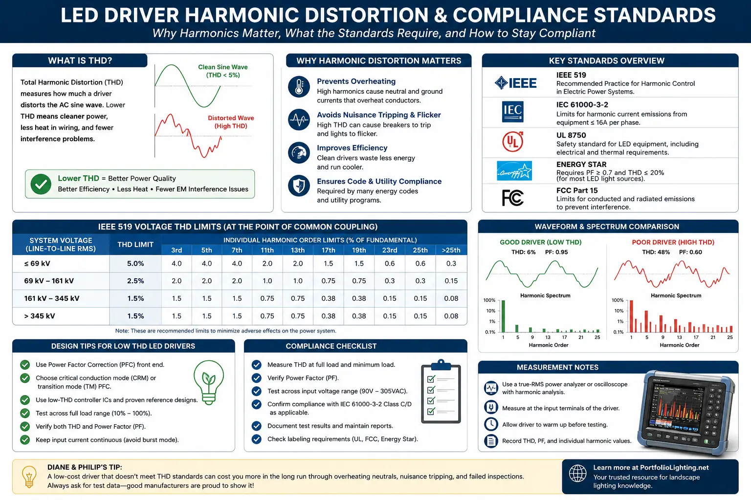
The Standards Map: Which Document Applies to Which Problem?
The most common compliance mistake is quoting one harmonic standard as though it governs every LED driver, every building, and every country. It does not. Product-level emission limits and system-level power-quality limits answer different questions.
| Standard or Requirement | Primary Scope | What It Evaluates | How It Relates to LED Drivers |
|---|---|---|---|
| IEEE 519 | Power system at the point of common coupling | Voltage and current harmonic distortion limits for the overall installation | Used by engineers and utilities to judge the combined effect of many nonlinear loads, not to certify one driver by itself |
| IEC 61000-3-2 | Equipment connected to public low-voltage systems, generally up to 16 A per phase | Limits harmonic current emissions by equipment class | Common product-compliance reference for lighting equipment in IEC markets |
| IEC 61000-3-3 | Voltage changes and flicker caused by equipment | Voltage fluctuation, flicker, and rapid load-change effects | Relevant when drivers, controls, or dimming cause visible supply fluctuation |
| ANSI lighting performance standards | North American lighting equipment performance | Driver and ballast performance requirements, including power quality in applicable documents | Often appears in commercial specifications and manufacturer data sheets |
| Project specification | The actual building, site, or owner requirement | THD, power factor, dimming range, surge immunity, flicker, and test conditions | Can be stricter than the minimum product standard |
Lighting Harmonic Compliance Matrix
| Standard | Typical THD Requirement | Primary Focus | Typical Application |
|---|---|---|---|
| ANSI C82.77 | Typically 20% or lower for many commercial drivers | Solid-state lighting power quality | Commercial lighting specifications |
| IEC 61000-3-2 Class C | Individual harmonic current limits | Equipment harmonic emissions | European lighting products |
| IEEE 519 | System-level harmonic limits at the Point of Common Coupling (PCC) | Utility power quality | Commercial and industrial facilities |
| California Title 24 | Project-specific driver performance requirements | Energy efficiency | California construction projects |
Why Harmonic Distortion Matters in Real Lighting Systems
In a small residential installation, one driver with mediocre THD may never cause a visible problem. The same driver repeated 30, 100, or 500 times can produce a very different result.
Neutral conductor heating
Triplen harmonics such as the third harmonic can add in the neutral of three-phase, four-wire systems instead of canceling. That can produce neutral current larger than expected from the phase current alone.
Transformer noise and heat
High crest factor and harmonic current increase eddy-current and stray losses. A transformer can buzz or run hotter even when the measured real-power load looks modest.
Generator and inverter instability
Portable generators and small inverters have less stiffness than utility power. Peaky LED driver current can distort the output voltage enough to make other drivers flicker or reset.
Control and dimmer problems
Phase-cut dimmers, occupancy sensors, photocells, and electronic relays may misfire when the driver input stage draws current in narrow or irregular pulses.
These symptoms are often misdiagnosed as bad lamps. The useful clue is repetition: if one model of driver behaves poorly across several fixtures while another driver remains stable on the same circuit, the problem is likely electrical compatibility rather than fixture wiring.
For related diagnosis, see the landscape lights flickering guide, transformer buzzing guide, and landscape lighting from a generator guide.
Why Low-Voltage Landscape Lighting Behaves Differently Than Line-Voltage LED Systems
A 12-volt landscape lighting system and a 120- to 277-volt commercial lighting system may both use LED drivers, but they do not respond to harmonic distortion in the same way. Understanding those differences explains why some inexpensive replacement lamps perform perfectly in one installation while creating flicker or transformer noise in another.
Magnetic Landscape Transformers Naturally Filter Some Harmonics
Traditional laminated iron-core landscape transformers behave as inductive filters. Their magnetic characteristics naturally reduce some high-frequency harmonic content before it reaches downstream LED replacement lamps. Although they are not designed specifically as harmonic filters, their construction often masks problems that become obvious on electronic power supplies.
Electronic Transformers Can Produce More Complex Waveforms
Modern electronic transformers switch at much higher frequencies than traditional magnetic transformers. The LED driver's bridge rectifier and input capacitor must process this higher-frequency waveform before regulating current to the LEDs. Depending on the transformer design, driver design, and connected load, this interaction may increase electrical noise, produce audible buzzing, or create unstable dimming behavior.
THD, Power Factor, Crest Factor, and Efficiency: Four Different Numbers
These values are frequently bundled together in marketing, but they describe different behavior.
| Metric | What It Tells You | What It Does Not Tell You |
|---|---|---|
| Current THD | How distorted the input current waveform is | It does not directly state efficiency or voltage distortion |
| Power factor | How effectively apparent power is converted into real power | A high value does not automatically guarantee low harmonic distortion |
| Crest factor | How high the current peak is compared with RMS current | It does not identify which harmonic orders dominate |
| Efficiency | How much input power becomes usable LED output | An efficient driver can still have poor input-current waveform quality |
A good commercial specification should require more than “high power factor.” It should state the minimum power factor, maximum current THD, test voltage, full-load operating point, dimming conditions, and whether the value applies to the driver alone or the complete luminaire.
How Premium LED Drivers Reduce Harmonic Distortion
Passive Power Factor Correction
Lower-cost LED drivers often rely on passive power factor correction using inductors and capacitors to smooth portions of the input waveform. Passive filtering improves performance but typically cannot maintain very low harmonic distortion across wide voltage ranges or varying loads.
Active Power Factor Correction
Higher-end commercial LED drivers use active power factor correction. Instead of simply filtering incoming power, an electronic controller continuously adjusts the input current so it more closely follows the incoming sinusoidal voltage waveform. This approach allows many premium drivers to maintain high power factor while also reducing current harmonic distortion to well below that of basic driver designs.
Commercial Portfolio fixtures often concentrate many electronic drivers on the same branch circuit, so replacement decisions affect more than light output. Current THD, power factor, inrush current, dimming behavior, output-current regulation, and emergency operation can all influence the finished system. The Portfolio commercial lighting guide shows where those driver specifications appear in older product codes and how to preserve the original electrical and control design when a driver or LED engine is replaced.
Why LED Driver THD Often Gets Worse When the Lights Are Dimmed
A driver that measures well at 100 percent output can behave very differently at 50 percent, 10 percent, or minimum dim. That is why one full-load THD number is not enough for a heavily dimmed project.
At low output, many drivers draw shorter, narrower current pulses. Real watts fall, but the waveform can become less sinusoidal. Current THD therefore may increase even though the absolute harmonic current is lower.
Phase-cut dimming adds another layer. The dimmer intentionally removes part of each AC cycle. The driver then has to interpret a chopped waveform while maintaining regulated LED current. Some combinations remain stable. Others produce audible noise, visible flicker, dropout, or repeated restart behavior.
For dimmer compatibility problems, use the LED dimmer compatibility guide and LED flicker troubleshooting guide.
Field Testing an LED Driver for Harmonic Problems
A normal clamp meter is not enough. It can show RMS current, but it cannot reliably tell you the harmonic spectrum or current waveform shape. Use a power-quality analyzer, harmonic analyzer, or bench power analyzer designed for nonlinear loads.
- Test the actual installed configuration. Include the dimmer, control, transformer, generator, or inverter that will be used in service.
- Warm the driver first. Run the lighting for at least 20 to 30 minutes so the driver reaches a stable operating condition.
- Record supply voltage and voltage THD. A distorted source can make the driver look worse than it is.
- Measure current THD and individual harmonic orders. The third, fifth, seventh, ninth, and eleventh harmonics are often the most useful starting points.
- Repeat at multiple dimming levels. Do not assume full-load behavior represents the entire operating range.
- Test a group, not only one unit. Small driver-to-driver variation can become important when dozens are connected together.
If a driver is stable on utility power but flickers on a generator, compare voltage THD with and without the lighting load. If voltage distortion rises sharply after the drivers are connected, the source impedance and driver current waveform are interacting.
Step-by-Step Field Diagnostic Protocol for Measuring LED Driver Harmonic Distortion
When a lighting system begins producing unexplained transformer noise, nuisance breaker trips, LED flicker, or electronic interference, measuring harmonic distortion provides far more useful information than checking voltage alone. A standard multimeter cannot measure individual harmonic components, so diagnosing these problems requires the proper test equipment and a consistent measurement procedure.
Step 1: Use the Correct Test Equipment
For meaningful harmonic analysis, use a true power-quality analyzer or an advanced harmonic clamp meter capable of measuring individual harmonic orders. Instruments similar to the Fluke 345, Fluke 435 series, or equivalent commercial power analyzers can separate the fundamental current from higher-order harmonics and calculate Total Harmonic Distortion automatically.
Step 2: Measure Under Actual Operating Conditions
Allow the driver to warm to normal operating temperature before recording measurements. If the driver supports dimming, record values at full output, approximately 50% output, and minimum stable dimming because harmonic performance often changes dramatically throughout the dimming range.
Step 3: Compare Current THD Using the Standard Formula
| Current THD Formula | THDI = √(I22 + I32 + I42 + ... + In2) ÷ I1 |
The numerator represents the combined RMS value of all harmonic current components, while I1 is the RMS current of the fundamental 60 Hz waveform.
Field Interpretation Guide
| Measured Current THD | Typical Field Observation |
|---|---|
| Below 10% | Excellent waveform quality typically associated with premium active power-factor-corrected drivers. |
| 10–20% | Suitable for most commercial lighting systems. Minor transformer heating may be observed under heavy loading. |
| 20–30% | Transformer hum, audible magnetics, and compatibility issues become more likely depending on system size and source impedance. |
| Above 30% | Poor waveform quality. Additional engineering review is recommended because higher harmonic currents can contribute to excess heating, driver stress, and compatibility problems in larger installations. |
Specification Language That Prevents Ambiguous Driver Claims
Instead of writing “low-harmonic LED driver,” use measurable language. The following is a practical starting point for a commercial or high-quality residential specification:
For more demanding projects, tighten the full-load THD requirement and require harmonic data across the dimming range. Also request surge immunity, inrush current, minimum load, maximum connected driver count per control, and acoustic-noise performance.
Do not accept a power-factor number measured only at nominal full load if the lighting is expected to spend most of its operating hours dimmed.
When Harmonic Distortion Is Probably Not the Main Problem
Not every flickering or buzzing fixture is a harmonic problem. Loose connectors, voltage drop, water intrusion, overloaded transformers, and incompatible AC/DC output are more common in small landscape systems.
Suspect harmonics when the problem affects many electronic drivers at once, becomes worse as more LED loads are added, appears only on generator or inverter power, changes with dimming level, or produces neutral/transformer heating that does not match the measured real watts.
For ordinary low-voltage wiring issues, start with the landscape lighting voltage drop guide, low-voltage connector guide, and transformer troubleshooting guide.
LED Driver Harmonic Distortion FAQ
What is a good THD number for an LED driver?
Below 20 percent at full load is a common minimum project target. Better drivers may stay below 10 percent. The correct requirement depends on the product standard, project type, connected quantity, dimming range, and local engineering requirements.
Can a driver have high power factor and still have high THD?
Yes. Power factor is broader than harmonic distortion. Always request both numbers rather than treating power factor as proof of a clean current waveform.
Why do LEDs buzz more on a generator?
A generator has higher source impedance than the utility. Peaky LED driver current can distort the generator voltage waveform, causing magnetics, capacitors, and dimmers to vibrate or operate irregularly.
Does UL listing guarantee low harmonic distortion?
No. Safety listing and power-quality performance are different. A listed driver may still have THD that is unacceptable for a specific project specification.
Standards and Safety Note
This page is an educational planning guide, not a substitute for the current text of IEEE, IEC, ANSI, UL, utility, project, or local electrical requirements. Standards editions and adoption rules change. Confirm the exact edition required by the authority, owner, engineer, or certification body before using any numerical limit in a contract document.