
Three Portfolio LED Configurations: Identify Yours Before Testing Anything
Before performing any bypass test, you must correctly identify which configuration your Portfolio fixture uses — because each configuration has different testability, different failure modes, and different repair options. Bypassing a potted non-serviceable fixture is impossible without destroying it; bypassing a replaceable-lamp fixture is unnecessary because you simply swap the lamp.
Open the fixture and you see a removable lamp — most commonly an MR16 (2-inch diameter, two-pin base) that pulls or twists out of a socket. The lamp contains its own miniaturized driver circuit and LED chips in one self-contained package. The socket inside the fixture body is simply a holder — no separate driver circuit is inside the fixture housing.
Failure mode:The lamp fails as a unit. Both the driver circuit and LED chips are inside the lamp. When it fails, replace the entire lamp ($5–20 for a quality MR16 LED).
Bypass test needed?No — there is nothing to bypass. If the voltage at the socket is correct and the lamp still doesn't light, the lamp has failed. Replace the lamp. See the Portfolio MR16 replacement guide and the LED modules and drivers replacement guide.
Open the fixture and you see: (1) an LED board — a flat PCB with LED chips soldered or bonded directly to it, no removable lamp, and (2) a separate driver module — a small circuit board or encapsulated block with wires going to the LED board and wires coming from the input power supply. The driver is a separate, physically distinct component connected by wires, not molded into the housing.
Failure mode:Either the driver or the LED board can fail independently. The driver fails far more often. The bypass test isolates which component has died before purchasing any replacement.
Bypass test needed?Yes — this is the configuration this guide addresses. The driver can be bypassed for testing and potentially replaced.
Open the fixture (if you can) and the interior is filled with black or gray epoxy or silicone compound. No visible circuit boards, no accessible wires, no identifiable components. The entire electronics assembly has been encapsulated in potting compound during manufacture. Alternatively, the fixture has no access cover at all — the housing is sealed as a single unit.
Why potted?Per industry documentation: "Fully potted integrated LEDs minimize entry points for moisture to enter internal components" — typically used in wet-location and marine landscape applications.
Bypass test needed?No — and impossible without destroying the fixture. If the power supply is confirmed correct and the fixture is dead, replace the fixture. See the Portfolio replacement guide and Portfolio landscape troubleshooting.
Why Drivers Fail Before LED Boards: The Capacitor Degradation Mechanism
Understanding why drivers are the primary failure point in integrated LED fixtures explains why the bypass test succeeds so often — and why the LED board is worth testing before assuming the whole fixture needs replacement.
The Electrolytic Capacitor Problem
LED drivers convert 12V AC (from the landscape transformer) or 120V AC (from mains) into the specific DC voltage and constant current that the LED board requires. This power conversion requires energy storage components — primarily electrolytic capacitors. Unlike ceramic capacitors or solid-state components, electrolytic capacitors are chemical devices: they store energy by maintaining a thin oxide layer on aluminum foil, kept in place by a liquid electrolyte.
The electrolyte has a finite life that degrades exponentially with temperature. At the rated temperature of 85°C, a standard electrolytic capacitor may be rated for 2,000 hours. Every 10°C reduction in operating temperature roughly doubles the capacitor's service life. But LED drivers in outdoor landscape fixtures run warm — power conversion is not 100% efficient, and the heat generated by the driver itself, combined with summer ambient temperatures, can push capacitor operating temperatures into the 60–75°C range even on a mild day. Over 3–5 years of outdoor operation in warm climates, the electrolytic capacitors inside the driver progressively fail — first causing increased voltage ripple (visible as flickering), then output voltage instability, and finally complete failure.
The LED Board Is Usually Fine
LED chips are solid-state light emitters with no chemical degradation mechanism. A properly driven LED chip — supplied with the correct constant current and protected from overvoltage — can operate for 50,000+ hours without significant lumen depreciation. In a Portfolio integrated LED landscape fixture that has been operating for 4–6 years and has just died, the LED board has typically accumulated far fewer than its rated operating hours. The driver, however, may have exhausted its electrolytic capacitor service life entirely.
Per EngineerFix documentation: "If your LED bulbs keep burning out earlier than expected, the real cause may be a malfunctioning LED driver that's supplying unstable current. Excess current flow overheats the LED chips, drastically shortening their lifespan." A failing driver doesn't just stop working — in its degradation phase, it may supply incorrect current that progressively damages the LED chips. This is why catching a driver failure early (at the flickering stage) is better than waiting for complete death — by then the LED board may also have been damaged by unstable driver output.
Visual Inspection First: What to Look For Before Any Electrical Test
Before reaching for a multimeter, a thorough visual inspection of the opened fixture can confirm driver failure in seconds — or identify LED board damage that makes the bypass test unnecessary. Per NeoLEDHub's driver failure documentation: "Visual inspection matters more than people think. Bulging capacitors, cracked solder joints, blackened board areas, and heat damage around power components often tell the story before the meter does."
Capacitor Bulge — The Most Reliable Visual Indicator
Electrolytic capacitors are cylindrical components, typically 5–15mm in diameter, with a flat or slightly indented top when healthy. When they fail or are near failure, the internal pressure from electrolyte breakdown causes the top of the capacitor to bulge outward — forming a dome or blister. This bulging is clearly visible under good light and is the single most reliable visual indicator of driver failure in integrated LED fixtures.
Look for the cylindrical components on the driver board — usually the tallest components present, arranged in a row or cluster. Compare their tops to the side profile: a healthy capacitor has a flat or slightly concave top. A failing capacitor has a distinctly convex, domed, or split top. Even a slight bulge is significant — a slightly bulging capacitor is failing even if the fixture still occasionally works. A split or venting capacitor (with visible electrolyte residue around the base) has fully failed.
Scorch Marks, Burn Patterns, and Discoloration
HENGWEI's driver failure documentation describes: "Burnt smell, melted casing, or charred components are clear indicators of total driver failure." Look for: dark discoloration on the driver board surface (brown or black staining that looks like a burn or scorching); any melted plastic on the driver housing or the fixture housing near the driver; and particularly for solder joint cracking or cold joints on the driver's input terminals — the points where the AC input wires connect to the driver board are under thermal stress from current flow and repeated heating/cooling cycles.
LED Board Visual Check
Also inspect the LED board during the visual inspection phase:
- Dark or discolored LED chips: Individual LED chips that appear dark brown, black, or physically damaged indicate dead LEDs on the board. A few dead chips may not prevent the board from illuminating (some boards continue with multiple dead chips), but extensive chip death means the LED board itself needs replacement.
- Phosphor degradation: Yellowing or darkening of the white phosphor coating over the LED chips is a sign of thermal damage from prolonged operation — which can be caused by years of normal use OR by a failing driver that supplied excess current.
- Cracked PCB or delamination: Physical damage to the LED board's substrate — typically from moisture infiltration and freeze-thaw cycling — indicates structural failure that no driver replacement will fix.
The capacitor bulge diagnosis correctly identifies driver failure in about 70% of the integrated LED fixtures I see. Open the fixture, find the driver board, look at the tops of the cylindrical components. If any of them are domed rather than flat, stop right there — you have your answer. The driver has failed and the LED board is almost certainly fine. I still run the bypass test to confirm before ordering the replacement driver, but the visual already told the story. The other 30%: driver with no visible damage but dead output (usually a failed internal component that doesn't produce visible bulging), or LED board failure. For those I go to the multimeter tests.
The Four-Test Bypass Sequence: Systematic Isolation Before Spending Anything
Run these four tests in sequence, stopping when you get a definitive result. Most failures are diagnosed at Test 1 or Test 2. Tests 3 and 4 are for cases where the problem isn't upstream of the driver.
PASS: Correct voltage present — continue to T2 FAIL: No or low voltage — problem is upstream, not in the fixture. Check transformer output, wire connections, and voltage drop. See the voltage drop guide and transformer testing guide.
Per HENGWEI documentation: "Use a multimeter in AC mode to confirm power at the input terminals (L/N). If input voltage is normal, but output reads 0V, the driver is likely defective." Expected DC output: check the driver label for rated output voltage (common: 12V DC, 24V DC, or a specific constant-current voltage range). A reading near the rated output means the driver is producing voltage. A 0V reading with correct input confirms driver failure.
Output = 0V with correct input → Driver has failed → Proceed to bypass test (T3) to confirm LED board health Output ≈ rated voltage → Driver is producing output → Proceed to T4 (LED board may have failed)
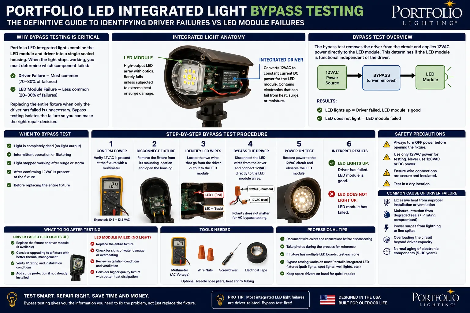
Disconnect the driver's DC output wires from the LED board's input terminals. Note which wire is positive and which is negative (photograph before disconnecting). Connect a regulated external DC power supply — a bench supply, a known-good LED driver of matching specifications, or a battery at appropriate voltage — directly to the LED board's input terminals, observing correct polarity.
Target voltage: check the LED board label if present. If unlabeled, start at the driver's rated output voltage (from the driver label). For most Portfolio low-voltage landscape integrated LED boards: try 12V DC first. Apply power and observe.
LED board illuminates → Board is functional. Only the driver has failed. Driver replacement will restore the fixture. LED board does not illuminate under direct supply → LED board has also failed. Replace the fixture.
If connections are good: measure the driver output voltage under load. Some drivers enter "hiccup mode" when connected to an open-circuit LED board — they produce output voltage when probed but drop to near-zero under the actual LED load because an internal overcurrent protection trips. Connect a simple resistive test load (a 12V incandescent lamp, an equivalent resistor) across the driver output — if voltage collapses under this test load but was present with just the multimeter, the driver is in protection mode and is likely degraded.
If driver output holds steady under test load but LED board still doesn't light: disconnect the LED board and test it directly with the external supply (same as T3). A non-illuminating LED board with correct supply voltage directly applied confirms LED board failure.
LED board fails direct supply test → Replace the fixture (both components are failed or board is failed) LED board passes direct supply test but driver collapses under load → Driver is in protection mode / partially failed → Replace driver
Constant-Current vs Constant-Voltage Drivers: Why the Distinction Determines Your Bypass Method
Before applying any voltage to the LED board in the bypass test, you must identify whether the original driver is constant-current (CC) or constant-voltage (CV) — because applying the wrong type of supply to an LED board can destroy it or produce misleading results.
A constant-current driver regulates its output to deliver a fixed current regardless of voltage. The LED board's operating voltage varies with temperature and LED forward voltage, but the current stays constant — which is what actually determines LED brightness and prevents thermal runaway.
How to identify on the driver label:Label shows output in milliamps or amps — e.g., "350mA," "700mA," "1.0A." The output voltage is shown as a range rather than a fixed value — e.g., "6–36V DC @ 350mA." This voltage range means the driver provides whatever voltage is needed to maintain the specified current through the LEDs.
How to bypass safely:A constant-current LED board cannot be safely tested with a constant-voltage bench supply at an arbitrary voltage — applying fixed voltage to a CC LED board produces uncontrolled current that can destroy the LED chips. You need either another CC driver of the same rated output (mA), or a bench supply in constant-current mode set to the driver's rated mA output. If you only have a CV supply, use a current-limiting resistor in series to approximate CC conditions — only for diagnostic purposes, briefly.
A constant-voltage driver regulates to a fixed DC output voltage — the LED board has current-limiting resistors or a separate constant-current circuit built into its design. The driver provides fixed voltage; the board manages current internally.
How to identify on the driver label:Label shows a fixed output voltage — e.g., "12V DC," "24V DC." Current is shown as a maximum value — e.g., "12V DC, max 1A." This fixed voltage output is what a CV driver maintains regardless of load variations.
How to bypass safely:Constant-voltage LED boards can be safely tested with a regulated CV bench supply or a known-good CV driver at the exact rated voltage (12V or 24V). Most consumer landscape lighting uses CV 12V DC systems because they're simpler to design. A 12V DC regulated supply (or a tested working Portfolio low-voltage landscape transformer with its output measured and confirmed at 12V) applied directly to a CV LED board's input is a clean, safe bypass test.
Multimeter Driver Test: The Three-Measurement Sequence
A multimeter is all you need to confirm driver failure before performing the bypass test. Three measurements, in sequence, give you complete information about driver status.
| Measurement | Meter Setting | Where to Probe | Expected Reading | Result Interpretation |
|---|---|---|---|---|
| Input voltage (AC) | AC Voltage, appropriate range (20V for LV landscape; 200V for 120V mains) | Driver's AC input terminals — the two wires coming from the supply/transformer to the driver input | LV landscape: 11.5–13.0V AC. Mains: 115–125V AC | Reading present = supply reaching driver. 0V = upstream supply problem — check transformer, wiring, connectors |
| Output voltage (DC), open circuit | DC Voltage, appropriate range (20V or 200V depending on driver output) | Driver's DC output terminals — the two wires going from driver to LED board (disconnect from LED board first) | Should match rated output voltage on driver label (e.g., 12V DC). For CC drivers: a voltage near the rated maximum of the output range | Reading near rated output = driver producing DC. 0V = driver has failed internally. Significantly low voltage (e.g., 8V when 12V expected) = driver degraded |
| Output voltage (DC), loaded | DC Voltage, same as above | Driver's DC output terminals while connected to LED board (or test load equivalent) | Should remain near rated output voltage under load. Some voltage sag is normal (<10%) | Voltage holds within 10% of rated = driver healthy under load. Voltage collapses to near-0 under load = driver in protection mode / thermal shutdown / overcurrent trip — driver is functionally failed. Significant fluctuation (5V to 10V cycling) = capacitor failure producing ripple — driver is failing |
The Load Test Reveals Hidden Driver Failures: A driver in "hiccup mode" — a protection state that some drivers enter when the LED board is damaged or shorted — produces normal output voltage when probed with a multimeter (because the meter's internal impedance is very high, presenting essentially no load) but drops to near-zero when the actual LED board is connected (because the LED board presents a real load). This is why probing the output with the LED board disconnected gives a deceptively healthy reading. Always also test with the LED board connected (or a test load) to catch hiccup-mode drivers that would otherwise appear functional.
The Bypass Procedure: Direct DC to LED Board, Step by Step
Once the multimeter test confirms driver failure (0V output or collapsed output under load), this procedure directly supplies the LED board from an external source to confirm the board is still functional before spending money on a replacement driver.
- Disconnect the transformer from its outlet (low-voltage systems) or turn off the circuit breaker (mains-connected fixtures) and verify de-energized with multimeter or non-contact tester. Never work on wiring with power applied — even 12V AC is not dangerous at typical landscape system currents, but energized wiring creates testing ambiguity and connection hazard.
- Open the fixture fully and photograph the internal wiring before touching anything. The photograph serves as your wiring reference for reassembly. Identify and label: the driver's AC input wires (from supply to driver); the driver's DC output wires (from driver to LED board); and the LED board input terminals (where the driver's output wires connect).
- Identify driver type (CC or CV) from the driver label. If the label shows a fixed voltage output (12V, 24V), it is CV. If it shows an output current in milliamps with a voltage range, it is CC. Match your bypass supply type to the driver type.
- Disconnect the driver's DC output wires from the LED board input terminals. Some fixtures use plug connectors (simply pull apart). Others have wires connected by wire nuts or small terminal blocks inside the fixture. Leave the driver's AC input wires connected to the transformer supply — the driver is still connected but its output is now disconnected from the LED board.
- Connect your external supply directly to the LED board input terminals, observing polarity. For CV 12V systems: a regulated 12V DC supply, a quality USB power adapter with DC output cable, or a small bench supply set to 12V works. For CC systems: another verified-working constant-current driver of matching mA rating. Connect positive to positive, negative to negative as photographed in step 2.
- Reconnect the transformer to the outlet (or restore circuit power) to energize the LED board through the external supply. If using a standalone bench supply: simply power the bench supply. Observe the LED board immediately.
- Interpret the result. LED board illuminates → board is functional, driver has failed, driver replacement will restore the fixture. LED board does not illuminate → either the board has also failed, or polarity is reversed. Try reversing the supply connections (if you're not 100% certain of polarity) and test again. Still nothing → LED board has failed.
- Disconnect power and reassemble. Remove the external supply connections, reconnect the driver's output wires to the LED board (or proceed to driver replacement if confirmed failed), and reassemble the fixture. This is a diagnostic procedure only — do not leave external supply connected as a permanent installation.
LED chips are diodes — they only conduct in one direction. Connecting an LED board with reversed polarity (positive to the negative terminal) applies reverse voltage across the LEDs. This does not cause immediate damage at low voltages (the LEDs simply won't light), but at higher voltages reversed polarity can destroy LED chips instantly. Always verify polarity from your photograph before applying any voltage. If wires are not color-coded and you don't have a photograph, use the multimeter's diode test function on the LED board's input terminals to confirm polarity (forward direction shows low resistance; reverse direction shows open circuit or very high resistance).
NEC Listing Implications: What Field Modification of a Listed Fixture Actually Means
This is the section that determines whether your repair is a code-compliant maintenance procedure or a code-problematic field modification. The distinction matters for insurance, inspection, and liability.
What NEC Section 411 and UL 1838 Require for Low-Voltage Landscape Lighting
NEC Section 411 governs lighting systems operating at 30V or less — which covers all standard 12V low-voltage landscape lighting. Per VOLT Lighting's published documentation: "NEC Section 411 requires that low voltage lighting equipment is UL listed for the purpose. This means that all electrical components (fixtures, wire, and transformers) carry UL Listings." The applicable listing standard for low-voltage landscape lighting systems is UL 1838 (Low Voltage Landscape Lighting Systems).
UL listing for a luminaire under UL 1598 (the luminaire standard) certifies the complete fixture as a unit — the specific LED board, the specific driver, and the specific housing as a tested, evaluated system. The listing belongs to the combination, not to any individual component.
What the Bypass Test Is (Diagnostic) vs What Field Modification Is (Code Problem)
The bypass test described in this guide is a temporary diagnostic procedure. The fixture is opened, a test supply is temporarily connected to confirm LED board function, and the fixture is returned to its original configuration. This is analogous to a technician temporarily disconnecting components to test them — it is maintenance diagnostic work, not permanent modification of the listed fixture.
A permanent driver replacement with an identical OEM driver is a like-for-like maintenance replacement — this is generally considered to maintain the listing because the replacement returns the fixture to its original listed configuration. If Portfolio originally installed a specific driver in a fixture and that driver is replaced with the identical driver specification, the fixture remains in its original listed configuration.
Replacing a failed driver with a non-OEM driver of different specifications is a field modification that voids the listing. Per the electrical forum documentation: "If you are altering a piece of equipment, call the manufacturer. The manufacturer will be able to tell you yay or nay, with an explanation." Substituting a different driver — even one with matching electrical specifications — changes the as-tested configuration and technically requires field certification by an NRTL (such as UL Field Evaluation) to restore listing status.
Repair vs Replace Decision Tree for Integrated LED Fixtures
Based on the test results and the practical constraints around Portfolio integrated LED fixtures, this decision tree determines the correct action.
Integrated LED Bypass Testing FAQ
My Portfolio integrated LED fixture flickers before going off completely. Is this the driver or the LED board?
Flickering before complete failure is almost always the driver in its degradation phase — specifically, electrolytic capacitors inside the driver developing increased resistance that produces voltage ripple on the output. Per HENGWEI's driver failure documentation: "If you notice flickering or inconsistent lighting in your LED setup, promptly diagnosing the root cause is essential. Start by measuring the output voltage using a multimeter. Should you observe notable fluctuations in this reading, it's an indication of driver issues." The flickering stage is actually the best time to diagnose and replace the driver — at this point the LED board is still healthy, and replacing the driver restores full function. Waiting until complete failure risks the degrading driver supplying erratic current that damages the LED chips, leaving you with two failed components instead of one. Open the fixture, run the visual inspection for capacitor bulge, and run the multimeter output test as described. See Portfolio LED lights flickering guide for the complete flickering diagnostic framework that covers all causes beyond just the driver.
The bypass test showed my LED board is good. Where do I find a replacement driver?
Finding replacement drivers for Portfolio integrated LED fixtures is the hardest part of this repair. Portfolio does not sell individual components. Your best sources in order: (1) Read the driver label completely — the manufacturer name, model number, and specifications are your search terms. Many drivers used in consumer lighting are made by generic manufacturers (Inventronics, Mean Well, OSRAM, Tridonic) and are available on Amazon, DigiKey, or Mouser under their own brand. (2) Search by electrical specifications if you cannot find an OEM match: input voltage, output voltage/current, physical dimensions, and connector type. A driver with identical electrical specifications from any manufacturer that physically fits the fixture can theoretically work — but see the NEC listing section regarding the code implications of non-OEM substitution. (3) The LED modules and drivers guide and the model number lookup may help identify compatible components for specific Portfolio models.
Can I permanently wire the LED board to an external transformer instead of replacing the driver?
Technically possible for constant-voltage 12V LED boards in a low-voltage landscape system — but there are two important caveats. First, as described in the NEC listing section, this permanently modifies the listed fixture, creating a non-listed assembly. For a residential DIY repair in a low-voltage landscape system that is unlikely to receive an inspection, this is a practical option some people choose — but it is not code-compliant for permitted work or commercial installation. Second, the external power supply must exactly match the LED board's requirements: voltage within ±5%, and current capacity that does not exceed the board's designed operating parameters. A landscape lighting transformer operating at 12V AC does not directly drive an LED board — you need 12V DC, which requires either a DC-output driver/supply or a bridge rectifier. The landscape lighting transformer's output is AC; the LED board requires DC. This is a critical distinction that many people get wrong and that causes immediate LED board failure. If you pursue this path, use a small 12V DC regulated power supply or LED driver, not the AC output of the landscape transformer directly.
My fixture has the LED board and driver combined on one single circuit board. Can I still bypass test it?
A combined driver-plus-LED-board on a single PCB is a specific integrated design where both functions are implemented in one unit — sometimes called a "COB module with integrated driver" or a "self-contained LED engine." In this configuration, there is no separate driver to bypass and no separate LED board to test independently. The bypass test cannot be performed as described. Your diagnostic is limited to: (1) confirming correct input voltage at the module's supply connections; (2) visual inspection of the module for burn marks, cracked substrate, or damaged LED areas; and (3) if the module connections allow it, comparing with a known-working identical module. If the module is dead with correct input voltage, replace the entire fixture. This configuration is common in lower-cost integrated LED landscape path lights and is the specific design that limits repairability, which is why the industry documentation notes: "fully potted integrated LEDs... are less efficient to maintain."
How do I prevent my integrated LED drivers from failing prematurely?
Three practices significantly extend integrated LED driver life in landscape fixtures: (1) Reduce operating temperature — heat is the primary enemy of electrolytic capacitors. Ensure the fixture housing has adequate ventilation, is not positioned in a sun trap, and is not buried in mulch or soil that traps heat. (2) Install surge protection — per the surge protection guide, surge events cause partial driver degradation even when they don't cause immediate failure. A surge protector at the transformer outlet addresses this. (3) Correct voltage — excessive input voltage stresses driver components. Verify transformer output is at the correct tap setting (11.5–12.5V at the transformer terminals) using the voltage drop calculator to ensure fixtures receive appropriate voltage. Most consumer landscape transformer failures traced to the transformer troubleshooting guide show some common root causes with integrated LED driver failures — surge events and heat.
Final Thoughts
Independent site not affiliated with Portfolio Lighting, Signify, or Lowe's. LED driver failure mechanism (electrolytic capacitor degradation) from EngineerFix LED driver replacement guide (engineerfix.com, November 2025) and Enoled LED driver replacement guide (enoled.com, March 2026). Driver vs LED board failure diagnosis from HENGWEI LED driver testing guide (hwele.net, November 2025) and NeoLEDHub driver failure symptoms (neoledhub.com, February 2026). Visual inspection protocol from NeoLEDHub: "Bulging capacitors, cracked solder joints, blackened board areas, and heat damage around power components often tell the story before the meter does." Driver type (CC vs CV) identification from Bravo Electro LED driver failure guide (bravoelectro.com). Hiccup mode / protection mode behavior from Hyperlite dimming troubleshooting guide (hi-hyperlite.com, February 2026). Integrated vs drop-in LED comparison from Brilliance LED (brillianceled.com) and Lighting Warehouse (lightingwarehouse.com, September 2022). Potted LED moisture protection from Brilliance LED contractor's perspective. NEC Section 411 low-voltage landscape listing requirement from VOLT Lighting UL listings guide (voltlighting.com) and EC&M magazine NEC low-voltage lighting article. UL 1598 and UL 8750 from PacLights LED electrical codes guide (paclights.com) and Smile Lighting certification guide (smilelighting.com, May 2026). UL field modification guidance from Mike Holt electrical forums and QTL Lighting UL recognized vs listed guide. NEC 410.6 luminaire listing requirement from general NEC reference. LED board polarity testing using diode function from LED Lighthouse multimeter guide (led-lighthouse.co.uk). This page is for educational purposes. Always de-energize circuits before working on electrical components. Permanent field modification of listed luminaires may void safety listings — consult the manufacturer or a licensed electrician before permanent modifications. NEC® is a trademark of NFPA. UL® is a trademark of Underwriters Laboratories.
Related Troubleshooting, Repair, and Parts Guides
- Portfolio Lighting Troubleshooting Hub
- Portfolio Landscape Troubleshooting
- Portfolio Landscape Lights Not Working
- Portfolio LED Lights Flickering
- Portfolio Lighting Too Dim
- Portfolio Lights Blinking
- LED Modules & Drivers Guide
- MR16 LED Replacement Bulbs
- Portfolio Bulb Replacement Guide
- Landscape Lighting Replacement Parts
- Portfolio Replacement Fixtures
- Path Light Replacement Guide
- General Landscape Troubleshooting
- Low-Voltage Failure Points Guide
- How to Test a Transformer
- Transformer Troubleshooting
- Voltage Drop Guide
- Voltage Drop Calculator
- Surge Protector Installation
- Surge Protection Guide
- Corroded Socket Cleaning
- Corrosion Guide
- Portfolio Model Number Lookup
- Maintenance Guide