
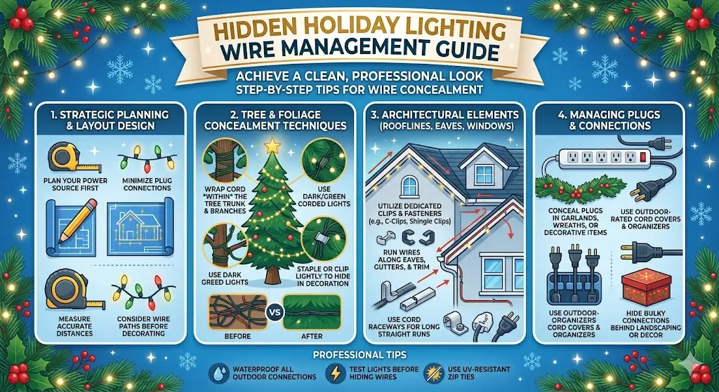
Step 0: The Pre-Install Power Plan (Non-Negotiable)
Professional holiday lighting installers do not touch a single strand of lights until they have a written power plan. This is the single discipline that separates clean professional installations from the messy amateur result — not skill, not tools, not even budget. The plan comes first.
What the Power Plan Contains
A complete pre-install power plan for holiday lighting documents four things: outlet locations, circuit assignments, total wattage per circuit, and wire path from each outlet to each display zone. You don't need drafting software — a rough sketch on paper works. What matters is having it before you start cutting, before you buy cords, and before you climb the first ladder.
- Mark every outdoor outlet on your home sketch. Walk the exterior and note the location of every outdoor GFCI outlet. Most homes have one at the front and one at the back per NEC requirements. Identify any garage outlets, workshop outlets, or outdoor outlet boxes that can reach the display area with appropriate cord lengths.
- Map your circuits. Plug a lamp or phone charger into each outdoor outlet. Go to the breaker panel and flip breakers one by one until the lamp goes out. Label which breaker number controls each outlet. This tells you which outlets share a circuit — critical for load calculation. Per Ferretti Lighting's professional guide: "Map your home's outlets before installation. Plug a small device into each and flip breakers one by one to identify which outlets belong together."
- Identify what else is on each circuit. Outdoor circuits often share breakers with garage outlets, basement lighting, or exterior security lighting. These loads count against your display budget. Note what's already running on each circuit before you plan display loads.
- Sketch the wire path from each outlet to each display zone. Trace the shortest, most concealed route from each outlet to the areas it will power. Note all transitions — vertical wall to horizontal soffit to downward downspout — and identify every surface type along the path. This is the routing map you'll follow during installation.
The Professional's Wire Path Principle: Follow architectural lines. Every roofline, gutter edge, downspout, window frame, door casing, and siding seam is a natural wire channel. The professional goal is not to "hide" cords — it is to route them along paths where they are structurally supported by the architecture and visually absorbed into existing edges and shadows. A cord running along the gutter back is structurally supported, thermally stable, and visually invisible from street level. A cord stretched diagonally across siding from one point to another is the opposite of all three. Always ask: is there an architectural line I can follow? The answer is almost always yes.
Circuit Capacity Math: The 80% Rule with Worked Examples
Every electrical circuit has a maximum capacity. Holiday lighting that exceeds that capacity produces tripped breakers, overheated cords, and in serious cases, fire. The 80% rule is the professional safety standard for calculating how much you can safely load onto any circuit.
How to Check Your Actual Loads
The wattage printed on a light string label is the rated wattage per strand, not per bulb. Add up the wattage of every strand and every decorative item you plan to connect to each circuit, including any non-holiday loads already on the circuit. A Kill-A-Watt meter plugged in-line gives you the actual measured draw rather than relying on label wattage — useful when mixing LED brands that may draw more or less than labeled.
Per the professional installer guidance from multiple sources: "Do not exceed 80% of breaker rating (e.g., max 1,440W on a 15A/120V circuit)." And from Ferretti Lighting: "If you're using LED lights rated at 40 watts per strand and you connect 20 strands, that's 800 watts, well within a 15-amp circuit's limit. However, incandescent bulbs draw significantly more, often limiting safe capacity to just a few connected strings."
Daisy-chaining — plugging one power strip or extension cord into another — is one of the most dangerous and most commonly cited holiday electrical fire causes. Each device has a maximum rated load; daisy-chaining can push the total load on the outlet connection far beyond what either device is rated for while masking the overload from the breaker. Per EcoFlow's holiday electrical safety guide: "Avoid 'daisy-chaining,' which is the practice of plugging one power strip into another. This creates multiple points of failure and increases the risk of a fire." If you need more outlets, run a separate extension cord from a different circuit outlet — not from an existing power strip.
| Light Type | Typical Watts/Strand | Strands on 15A Circuit (80% rule) | Notes |
|---|---|---|---|
| LED mini lights (50-ct) | 4–7W | 200–360 strands | LED is the clear choice for large displays; voltage drop and 250-ft run limit are the practical constraints, not circuit capacity |
| LED C7 retrofit | 10–18W | 80–144 strands | C7 cords wired in parallel; individual bulbs replaceable; more durable for long outdoor runs |
| LED C9 retrofit | 20–35W | 41–72 strands | Most common professional roofline light; 12″ socket spacing standard |
| Incandescent mini lights | 40–60W | 24–36 strands | Wired in series; single burned bulb can darken entire strand; significant heat generation |
| Incandescent C7 (7W bulbs) | ~100W/10-bulb section | ~14 sections | Heavy draw; creates the case for LED C7 retrofit on existing parallel C7 wire infrastructure |
Cord Selection: Outdoor Ratings, Gauges, and the SPT Wire Option
Not all extension cords are equal for outdoor holiday use. Using the wrong cord type or gauge is a common cause of overheating, GFCI trips, and fire — and many hardware store extension cords sold near holiday displays are actually indoor-rated products that fail under outdoor conditions.
Outdoor Cord Ratings — What the Labels Mean
Outdoor-rated extension cords carry specific designation letters in their cord type classification. Per Nassau National Cable's NEC Article 400 guide: cords for outdoor use must be water-resistant. "Cords such as SOOW or SEOOW must be selected, as they feature jackets and insulation rated for moisture exposure." For holiday lighting, look for these common outdoor designations:
- SJTW: Junior hard service, thermoplastic, weather-resistant. The most common residential holiday extension cord type. Suitable for most residential outdoor applications in moderate climates.
- SJOOW: Junior hard service, oil-resistant outer jacket, weather-resistant. More durable than SJTW; better flex retention in cold temperatures. The "W" suffix indicates wet location suitability.
- SJOW / SOW: Hard service (heavier than junior), oil-resistant, weather-resistant. Professional installer grade — the cords used by commercial holiday lighting companies. Rated for -40°F to 140°F per the professional installer field guide specification.
- SPT-1 / SPT-2: Parallel lamp cord (flat, two-wire construction). Used to build custom holiday light cords. SPT-1 (18 AWG) for light loads; SPT-2 (18 AWG with heavier jacket) for exposed runs or mechanical stress.
Wire Gauge and Run Length
Gauge determines how much current a wire can carry safely and how much voltage drops over distance. Per the professional installer guidance from Christmas Designers: cords for runs over 25 feet should be 14-gauge or 12-gauge to prevent voltage drop and overheating. Per the Christmas Light Source professional reference: "Also confirm that your cord length (of a 10-amp 18 AWG wire) is not longer than 250 feet for 18 AWG wire." For runs beyond 50 feet with significant incandescent loads, step up to 16 AWG minimum. For runs beyond 100 feet, 14 AWG is the professional standard.
| Wire Gauge (AWG) | Max Recommended Run | Max Load | Best Use Case |
|---|---|---|---|
| 18 AWG (SPT-1) | Up to 100 ft for LED | ~7A (840W) | Custom SPT cord runs for LED strings; short jumpers between zones |
| 16 AWG | Up to 150 ft | ~10A (1,200W) | Standard residential holiday extension cords; medium-length runs with mixed loads |
| 14 AWG | Up to 200+ ft | ~15A (1,800W) | Long runs to distant trees; main feed cord from outlet to distribution point; large incandescent displays |
| 12 AWG | Up to 300+ ft | ~20A (2,400W) | Commercial installations, very long runs, high-load incandescent displays |
Building Custom SPT Cords with Vampire Plugs
The single biggest upgrade from amateur to professional-looking holiday wire management is building custom SPT cords cut to exact length instead of using store-bought extension cords. Custom cords have zero slack, follow the path exactly, and connect to light strings without any excess cord to hide. The Christmas Light Emporium's professional guide calls this "the clean infrastructure" approach.
What You Need
- SPT-1 or SPT-2 wire: Available in 250-foot and 500-foot spools in white and green (white for white trim, green for landscaping and dark surfaces). SPT-1 for light LED loads; SPT-2 for mechanical exposure, foot traffic areas, or outdoor runs that may contact ice.
- Vampire plugs (male): The plug that goes into the outlet or the female end of the previous cord. Called "vampire plugs" because they pierce the wire insulation with teeth. Match SPT-1 plugs to SPT-1 wire — they're not interchangeable with SPT-2.
- Inline female pass-through plugs: Create a tap point partway along a cord run — used to power a wreath, a tree, or a side zone without running a separate cord from the outlet.
- Weatherproof gaskets: Rubber ring seals that compress around the plug connection when joined to a female end. Per the Christmas Light Emporium: "weatherproof gaskets — plug gaskets (25-pack) seal every junction against moisture. Non-negotiable for outdoor use." A single unsealed outdoor connection in rain will trip a GFCI.
- Cable cutters and a marker: Clean cuts are essential for proper vampire plug seating. Mark polarity on the wire before you forget.
The Construction Process
- Measure before cutting. Stretch a tape measure or use a piece of string to trace the exact installed path of the cord — not the straight-line distance. Per the Christmas Light Emporium: "Measure the exact distance, then add 10–15% for drip loops and gentle bends." Mark the measurement on the spool.
- Identify the ribbed conductor before cutting. SPT wire has one smooth side and one ribbed side. The ribbed side is always the neutral conductor. Mark both ends of every length you cut — a Sharpie mark on the ribbed side at each end. Per the Christmas Light Emporium: "consistent polarity through every plug matters."
- Cut cleanly with cable cutters. Ragged cuts make plug attachment harder and can mis-seat the vampire teeth.
- Attach the male plug at the supply end. Open the plug body, lay the wire with the ribbed conductor aligned to the wider (neutral) blade, and press firmly until the teeth pierce the insulation. The plug body should snap fully closed with no gap.
- Attach female ends or inline taps. For a simple extension cord, attach a female plug at the other end. For a trunk line with multiple tap points, slide on inline female pass-throughs at each branch location. Polarity stays the same — ribbed conductor to neutral — every time.
- Add weatherproof gaskets at every connection point. Slide a gasket over the male plug before the first test. When the male and female ends are joined, the gasket compresses between them, sealing the connection against water infiltration.
- Test before deployment. Plug into a GFCI outlet with a small load (a single light string). Verify the connection works, no GFCI trips, and no warmth along the cord after five minutes.
The Custom Cord Advantage: A custom SPT cord run from outlet to the start of the C9 roofline has zero excess length. It lies flat against the siding or inside the gutter with no bunching, no extra loops to tuck, and no extra length creating trip hazards. Vampire plugs are inexpensive — a few cents each. At the end of the season, the cord goes into a labeled bag, ready to be re-deployed next year in exactly the same path in under 10 minutes. This is the hidden infrastructure that makes professional installations look effortless and reinstall quickly.
Surface-by-Surface Routing: Vinyl, Wood, Brick, Stucco, and Metal
Different exterior surface materials require different routing techniques and fastener types. Using the wrong fastener damages the surface, fails under thermal cycling, or creates gaps where water infiltrates. This section covers each major residential surface type with specific techniques.
Vinyl siding offers three unique routing options unavailable on other surfaces. First, the J-channel technique: C7 and C9 light wire slides directly into the J-channel trim channel at the top edge of siding panels without any fasteners or hardware — the channel grips the wire. Per Christmas Light Contractors USA's vinyl guide: "C7 lights fit snugly into the vinyl siding's J-channels without the need for additional hardware." The wire tucks in at the start point and lies concealed inside the channel for the full run. Second, flat SPT wire can slide into the vertical seams between vinyl siding panels — the natural slot between overlapping panels is wide enough for flat cord and holds it firmly. Third, adhesive-backed outdoor clips (3M Command outdoor series) attach directly to smooth vinyl without drilling. For vertical runs down a vinyl corner post, clip every 12–18 inches. For all adhesive fasteners on vinyl: warm the surface with a heat gun for 30 seconds before application to activate the adhesive in cold weather. Per the professional installer guidance: adhesive clips "remove cleanly in spring with zero residue when warmed gently with a hairdryer."
Wood surfaces allow the most routing flexibility but require care to avoid splitting, water infiltration at fastener holes, and paint damage. Best practices: Use paintable PVC cord raceways (surface-mounted channels that snap over the cord) painted to match trim color — from street level these are effectively invisible when color-matched. Adhesive-backed outdoor clips on smooth painted wood surfaces hold well when applied in dry conditions above 40°F. Never use staples or nails driven through the cord insulation — these create electrical shorts and fire hazards. Per the professional installer guidance: "Use stainless steel conduit straps with rubber grommets or UV-resistant nylon cable clips rated for -40°F to 140°F. For wood surfaces, pilot holes prevent splitting." Space fasteners every 18–24 inches. For the soffit underside (horizontal wood beneath the eaves), run cords along the back edge closest to the fascia where they're in shadow and supported by the structural joint. For wood porch columns, use adhesive cable clips spaced every 15 inches running vertically from the outlet to the roofline.
Brick cannot accept adhesive fasteners well — the rough porous surface prevents adhesive bonding. Use mortar-line clips: small plastic clips specifically designed to sit in the mortar joint between brick courses, holding cords flat against the brick face without any drilling. Alternatively, for permanent or semi-permanent runs, small masonry anchor screws with rubberized cable clamps provide secure attachment. Drill pilot holes in mortar joints (never through bricks) using a masonry bit, seal the hole with silicone after the anchor is placed. Per the professional installer guidance: "For brick or stucco, use brick clips or zip ties coupled with small masonry nails — offer a secure anchor." Per Christmas Light Emporium on brick entryways: "hot glue works well on brick, stone, and unpainted concrete. Painted surfaces and stucco are susceptible to damage from hot glue, so double-check your surfaces before application." For a completely non-invasive approach on brick: run cords inside the natural shadow line along the top edge of the brick foundation, where they're concealed by the projection of the brick course above and require no fasteners.
Stucco and EIFS (Exterior Insulation and Finish System) are the most damage-sensitive exterior surfaces for holiday wire management. Adhesive fasteners pull off stucco finish, hot glue damages stucco, and staples create cracks. The correct approach: route all wires along non-stucco surfaces adjacent to stucco (window frames, door casings, soffits, gutters) and avoid attaching anything directly to stucco surfaces. Where a vertical stucco run is unavoidable, use low-profile PVC raceways in a color that approximates the stucco color, attached with masonry anchors in the mortar line at the stucco base (if it has an exposed base course) or with stucco-specific clip systems. For EIFS specifically, any penetration requires careful caulking to prevent moisture infiltration into the foam board beneath — a professional's job.
Metal gutters, metal downspouts, metal siding panels, and metal HVAC units accept neodymium magnetic cable holders that attach and remove without any fasteners, adhesives, or surface impact. Per the professional cord hiding guide: "Magnetic cable holders work on metal gutters, downspouts, or HVAC units. These strong neodymium magnets have rubberized grips that hold cords securely without scratching surfaces." Neodymium holders are especially useful for temporary holiday use because they require no installation time and leave zero residue. On aluminum gutters (which are the most common residential material), standard ferrite magnets don't hold well — the neodymium grade provides adequate holding force. On painted or powder-coated metal surfaces, rubberized magnet faces prevent paint scratching. Space magnets every 18–24 inches for adequate support without sagging.
The Gutter Channel and Downspout Vertical Run Techniques
Two architectural features of nearly every residential roofline — gutters and downspouts — are the most effective wire concealment paths available to holiday light installers. Used correctly, they make power distribution at roofline level invisible. Used incorrectly, they create water-trapping safety hazards.
Gutter Channel Routing
There are two distinct ways to use gutters for cord routing, and they have different safety profiles:
- Inside the gutter (dry gutters only): The cord lies inside the gutter channel itself. This completely conceals the cord from below. The safety condition: the gutter must drain completely and dry between precipitation events, and must not be prone to ice damming. A cord submerged in standing water creates a shock hazard and will trip GFCI repeatedly. Clean gutters before the season. If your gutters retain water after rain, use the behind-the-gutter method instead. Per the professional installer guide: "Run cords behind gutters using plastic clips that grip the backside. If gutters are open, place cords inside — but only if they're dry and not used for drainage during winter thaws."
- Between gutter and fascia (all-weather option): The cord runs in the space between the back of the gutter and the fascia board behind it. This space is typically ½–1 inch wide on most residential gutters — enough to accommodate flat SPT cord or standard extension cord. This position is protected from precipitation hitting the cord directly, allows the gutter to drain normally, and is invisible from below. The professional installer manual from We Hang Christmas Lights specifically cautions: "Do not have your employees hide the connections in the gutter in an attempt to make it look more professional" — meaning connections should remain accessible and visible outside the gutter rather than being buried inside.
Downspout Vertical Runs
Downspouts create ideal vertical wire channels. A cord running from roofline level to ground level can travel behind a downspout rather than along a visible siding run. The technique: slide a flexible fish tape or straightened coat hanger behind the downspout (in the gap between the downspout and the wall) to create a guide wire, then use the guide to pull the SPT cord through. For metal downspouts, neodymium magnetic clips hold the cord against the downspout without inserting it behind. For vinyl downspouts, adhesive clips or small zip ties looped behind the downspout mounting strap grip the cord at each mounting point.
The downspout technique is the professional installer's vertical solution for every home style, and it works on every exterior material because you're attaching to the downspout, not the wall. On a two-story Craftsman with cedar siding, the main power feed runs from the GFCI outlet at the front corner behind the downspout all the way to roofline level — then along the back of the gutter to the start of the C9 run. From the street there's nothing to see except the gutter and the lights. The entire feed path is invisible. That single technique eliminates more visible wire than any other single decision in the installation plan.
Fasteners: What to Use on Each Surface and What to Never Use
The Fastener Spacing Rule
Space fasteners every 18–24 inches for standard cord runs, and every 12–15 inches for runs that will experience wind loading (roofline edges, exposed soffit runs). The spacing should be tight enough to prevent visible sagging between fasteners when viewed from street level, but not so tight that the cord is under tension — tension creates failure points at each fastener when the cord contracts in cold temperatures.
| Fastener Type | Best Surfaces | Temperature Range | Damage Risk | Removal |
|---|---|---|---|---|
| 3M Command Outdoor Clips | Smooth vinyl, smooth painted wood, metal | -20°F to 125°F | Zero — removable without residue | Warm with hairdryer; pull tab releases cleanly |
| UV-resistant nylon cable clips (screw-mount) | Any surface that accepts screws without damage | -40°F to 140°F | Small pilot hole required | Unscrew and fill hole with color-matched caulk |
| Neodymium magnetic holders | All ferrous metal surfaces only | -40°F to 150°F | Zero on metal surfaces | Pull off; instant removal |
| Mortar-line brick clips | Brick and stone (mortar joint only) | All temperatures | Zero — no adhesive, no drilling | Slide out of mortar joint |
| Gutter hooks (S-hooks) | Open-face gutters, closed gutters with access | All temperatures | Zero — no attachment to surface | Lift out |
| Insulated staple gun clips | Wood trim only (not siding or insulated panels) | Varies by product | Damages siding; can pierce cord insulation if misused | Must be pried out; may leave marks |
| Nails or screws through cord | NEVER | — | Fire and shock hazard — pierces cord insulation | Discard the cord; it is compromised |
| Standard duct tape or masking tape | NEVER outdoors — fails in 48 hours | Fails below 50°F | Leaves residue; fails in rain | Often impossible to remove cleanly |
Thermal Expansion Slack and Cold-Weather Wire Behavior
Extension cords and SPT wire expand when warm and contract when cold. A cord that fits perfectly at 60°F in November can become uncomfortably taut — enough to pull free from clips or pull on connections — at 10°F in January. Professional installers build slack into every run to accommodate this.
The Slack Rules
- Add 10–15% extra length when measuring SPT wire for custom cords. A 50-foot run needs a 55–57.5-foot cord. The extra length accommodates drip loops at connections plus thermal contraction allowance.
- Leave ⅛-inch gaps between sections of surface-mounted PVC cord raceways. Per the NEC standard for conduit (which uses identical thermal logic): raceway sections need expansion gaps to prevent buckling under thermal cycling. A rigid raceway with no expansion gap will gap open or warp when temperatures swing.
- Never install cords under tension. A cord stretched tight between two fastener points will pull the fasteners out or pull the plug from the connection when it contracts in cold weather. The cord should rest loosely in each clip, not be stretched between them.
- Drip loops must be sized for cold-weather contraction. A drip loop that looks generous at installation may pull almost flat at -10°F. The loop should have at least 4–6 inches of free cord arc at installation temperature to maintain the downward drip shape through the coldest expected night.
Cold-Temperature Cord Flexibility
Standard household extension cords become stiff and brittle at temperatures below 20°F. Forcing stiff cord around corners or into clips at these temperatures can crack the insulation — especially at connection points and bends. SJOOW-rated cords ("O" suffix indicates oil-resistant jacket which also improves cold-temperature flexibility) remain pliable to approximately -40°F. For installations in genuinely cold climates (Minnesota, upstate New York, mountain regions), specifying SJOOW or SOOW-rated cord eliminates cold-weather brittleness issues that cause mid-season failures on cheaper SJTW cords.
GFCI Protection and the Drip Loop: Two Non-Negotiable Rules
GFCI Protection Is Required — and Required to Work
Per NEC Article 210.8: all 15A and 20A outdoor receptacles require GFCI protection. Per Shaffer Construction's holiday safety guide: "Standard circuit breakers don't trip until current flow reaches 15 to 20 amps — thousands of times higher than what can kill a person. Only GFCI devices provide protection at the low current levels that prevent electrocution." This is especially critical for outdoor holiday lighting where cords are exposed to rain, snow, and ground moisture.
Before installing any holiday display, test every outdoor GFCI outlet you plan to use. Press the TEST button — power should cut immediately. Press RESET to restore. If the button doesn't click or power doesn't cut, the GFCI has failed and the outlet is not protected. Do not use it for holiday lighting. Install a replacement GFCI outlet (a DIY task for anyone comfortable with basic wiring) or have an electrician install one. Refer to the GFCI requirements guide for the full NEC specification and testing protocol.
The Drip Loop at Every Outdoor Connection
A drip loop is a deliberate downward arc in the cord at any outdoor connection point — before the cord enters a plug junction, receptacle, or weatherproof connector. Water runs downhill. Without a drip loop, water follows the cord directly into the connection. With a drip loop, water reaches the bottom of the arc and drips off harmlessly before reaching the connection.
The correct technique: route the cord up to the connection point from below, creating a natural U-shape with the connection at the top of the U. Secure the cord with a zip tie or clip on each side of the connection to maintain the loop shape regardless of wind. Per the professional installation guide: "Elevate the taped joint off the ground and secure it to your gutter or siding with a zip tie so melting snow or rain cannot pool around the plug." For connections at the base of a downspout (where the cord transitions from vertical to horizontal), create the drip loop at the transition point — the cord comes down the downspout, arcs downward, then runs horizontally to the outlet.
Ground-Level Runs: Walkway Crossings, Elevation, and Rodent Prevention
Crossing Walkways and Driveways
The most dangerous holiday wire management location is the ground-level crossing — any point where a cord must cross a pathway that people or vehicles will use. The options in order of safety and professionalism:
- Avoid it entirely. Rethink the display layout to power distant elements from a different outlet or run the cord over the walkway overhead (attached to a soffit or beam above the pathway). This is always the first-choice solution.
- Rubber cord ramps (pedestrian walkways). Heavy-duty rubber or polyurethane cord protectors lie flat on the surface and allow foot traffic to cross safely. For walkways, these are acceptable temporary solutions. Use ones with drainage channels to prevent water pooling under the ramp.
- Traffic-rated cord protectors (driveways). For any vehicle crossing, use cord protectors specifically rated for vehicle weight — typically 10,000 lbs or more per axle. Standard pedestrian cord ramps will crush under vehicle weight and may arc if the cord insulation is damaged under load. Per the professional guide: "use heavy-duty, traffic-rated cord protectors (rated for 10,000+ lbs per axle) with reflective striping for visibility at night."
- Never bury unprotected extension cords in soil. Per the professional guide: "Never bury extension cords in soil, mulch, or snow — even temporarily." Extension cords are not rated for direct burial. Moisture infiltration, rodent chewing, and ground shifting damage the insulation rapidly. If you need a buried run, it must be in conduit with properly rated UF cable — a permanent installation, not a temporary holiday cord.
Elevation: Keeping Cords Off the Ground
Cords that lie directly on the ground — even temporarily — are at risk from snow, standing water, and rodent damage. Professional guidance: "Elevate cords 2–4 inches above grade using adjustable landscape stakes fitted with cord cradles. This prevents water pooling, rodent chewing, and accidental shoveling damage." For garden bed areas where cords feed from a path light or a ground-level plug to a tree or shrub, stakes keep cords above the wet mulch surface throughout the season.
Rodent Deterrence
Squirrels and rodents are attracted to the plasticizers in cord insulation and will chew through extension cords. This creates a live electrical hazard with no warning. Prevention: use SJOOW cords (the "OO" jacket is oil-resistant and less palatable to rodents than standard SJTW jackets); route cords away from known rodent pathways like fence lines and garden edges where rodents travel; apply bitter-tasting cord deterrent spray (commercially available); and use metal conduit sections to protect any cord that runs along the ground in a rodent-prone area. Per the holiday lighting safety guide from Shaffer Construction: "Ensure storage areas are free from rodents, which may chew through wire insulation seeking nesting materials."
Cord Color Strategy: Matching Surface and Shadow
Cord color is the easiest, cheapest wire management upgrade that most homeowners completely ignore. The right cord color against the right surface reduces visible cord by 80% with zero installation effort.
| Cord Color | Best Surfaces | Where to Avoid | SPT Available? |
|---|---|---|---|
| Green | Lawn, mulch, garden beds, evergreen shrubs, tree trunks, cedar siding, dark-stained wood | White trim, light-colored brick, white stucco | Yes — standard SPT spool color |
| White | White vinyl siding, white wood trim, white gutters, white fascia, white stucco | Dark surfaces, brown wood, brick | Yes — standard SPT spool color |
| Black | Dark brick, dark siding, dark trim, asphalt areas, shadowed eaves, black gutters | White or light surfaces | Available but less common in SPT |
| Brown | Brown wood siding, brown trim, bark mulch, rustic or craftsman-style homes | White or light surfaces, modern homes | Specialty colors — less widely available |
| Gray / Silver | Concrete, gray brick, silver metal gutters and downspouts | Most other surfaces | Not standard; use black as alternative |
The Painted Raceway Option
For surfaces where no standard cord color provides adequate camouflage — complex multicolor stucco, painted brick, unusual siding colors — paintable PVC cord raceways accept latex exterior paint that matches any surface. Paint the raceway sections before installation, let dry fully, then install. The result is a cord channel that is essentially invisible because it matches the surface color exactly. This technique requires more preparation time but works on any surface and produces professional results even in challenging color environments.
Zone Splitting for Large Displays
Any display that covers more than one side of a house, or uses more than 200 strands of LED lights from a single outlet, needs to be divided into independent zones — each zone powered from its own circuit with its own cord infrastructure.
Why Zone Splitting Is Essential
- Voltage drop management: Runs exceeding 250 feet suffer voltage drop that reduces lumen output and can cause overheating at the far end of the run. Splitting into shorter zones per circuit keeps every run within safe voltage drop limits.
- GFCI troubleshooting: When a single GFCI protects the entire display and trips, every light goes dark. When the display is split into four independent zones, a GFCI trip from a faulty connection affects only one zone — the other three stay lit and the problem area is immediately identifiable.
- Load distribution: A display covering the front and both sides of a two-story house may draw 3,000–5,000 watts total — far beyond a single 15A circuit. Zone splitting distributes the load across multiple circuits, each staying within the 80% safety threshold.
The Professional Zone-Split Design
Per the Christmas Light Emporium's SPT wire guide: "Zone splitting — Dividing your display into independent circuits reduces voltage drop and makes GFCI trips easier to troubleshoot." The professional approach: plan zones before purchasing any cord or lights. Each zone is powered by a dedicated extension cord run from a specific outlet, and contains only the lights reachable within the 250-foot/200-bulb run limit from that outlet. Zone boundaries often follow natural architectural divisions: front roofline (Zone 1), left side and garage (Zone 2), right side and entryway (Zone 3), trees and yard (Zone 4).
For large displays on homes without adequate outdoor outlets, this is also the point to consider having an electrician add a dedicated outdoor outlet at a strategic location — often worth the $300–$800 installation cost for properties that display lights annually. See the GFCI requirements guide and junction box requirements for the electrical code requirements for new outlet installation.
Series vs Parallel Wiring: What It Means for Wire Runs
Holiday lights use two different internal wiring configurations, and understanding which type you're working with determines how you can cut, extend, and connect them — which directly affects wire management decisions.
Series-Wired Mini Lights (Most LED and Incandescent Mini Strings)
Per Christmas Light Source's technical guide: "Traditional incandescent and LED Christmas tree mini lights are wired in series. Series wired light strings cannot be cut and if one bulb is removed the rest of the string will go out." Series wiring means all the voltage from the supply drops across all bulbs in sequence. A 50-light series string operating at 120V distributes 2.4V per bulb. If one bulb fails, the circuit opens and the whole string goes dark.
Wire management implication: series strings cannot be cut to length — you must use the full string as manufactured. They also cannot have mid-string power injection. Plan all series-string runs to connect end-to-end without cutting. The maximum number of series strings per single plug connection varies by manufacturer — check the label, but typically 3–5 strings maximum end-to-end before exceeding voltage/load specifications.
Parallel-Wired C7 and C9 Cords
Per Christmas Light Source: "Traditional C7 and C9 cords are generally manufactured with heavy duty wire and are wired in parallel. Parallel wired lights can be cut and terminated to fit and if one bulb is unscrewed and removed, the rest will stay lit." Parallel wiring means each bulb (socket) is connected directly from line to neutral independently — the failure of one bulb creates no circuit break for adjacent bulbs.
Wire management implication: C7 and C9 parallel cords can be cut to exact length, terminated with a female end, and a new section started anywhere. This is why SPT wire custom building works so well with C7/C9: you build the exact-length socket wire run, add a female plug at one end and vampire plug the SPT feed to the other. Per the Christmas Light Emporium: "Custom jumpers eliminate messy extension cords across gutters and downspouts. Cut SPT-1 to the exact length from your outlet to the start of your socket line."
Cord routing directly affects C7 and C9 socket life. Pulling a flat holiday-light cord tightly around corners transfers strain into insulation-piercing socket connections, while clips placed against the socket body can twist the internal contacts whenever wind moves the string. The C7 and C9 holiday socket repair guide shows how loose cord connections, cracked housings, damaged backs, and mismatched SPT-1 or SPT-2 replacement sockets create intermittent failures that appear only after the display has been mounted.
7 Wiring Mistakes That Cause GFCI Trips
A GFCI trip at 6pm on Christmas Eve is the nightmare scenario. Most holiday lighting GFCI trips are preventable — and most are caused by one of these seven specific wiring mistakes.
The most common cause. A plug-to-plug connection lying flat on the ground accumulates water in the connection gap. When water bridges the contact gap between plug faces, current leaks to ground and the GFCI trips. Fix: elevate all connections 6 inches or more above ground level using landscape stakes or clips, and add drip loops at every connection. Never let a plug connection rest in snow or ice.
SPT wire vampire plug connections and C7/C9 inline connections are not inherently weatherproof. Rain water enters the open joint between male and female ends, reaches the contacts, and triggers the GFCI. The fix is a 5-cent weatherproof gasket at every plug junction. Per the Christmas Light Emporium: "Seal unused sockets with end caps — a single open female end in the rain will trip a GFCI faster than anything."
Many homeowners blame the GFCI when the breaker trips. A breaker trip cuts power to all outlets on the circuit, including the GFCI outlet — making it appear the GFCI tripped when the actual cause is overload. Test by pressing the GFCI reset button: if it resets and power restores, it was a GFCI trip; if pressing RESET doesn't restore power, the breaker tripped and the overload must be reduced. Fix: calculate circuit load per the 80% rule and stay below 1,440W on a 15A circuit.
A cord routed inside a gutter that subsequently fills with water and freezes creates a cord submerged in water-ice during partial thaw cycles. As the ice melts and refreezes, water infiltrates every cord connection and crack in the insulation. Fix: if your gutters ice dam in winter, route the cord in the space between the gutter back and fascia instead of inside the gutter channel.
Running a cord through a window gap or under a door weatherstrip for power access is convenient but dangerous. The trim or door compresses the cord insulation, creating internal wire deformation that can cause current leakage, GFCI trips, or sustained arcing. Per NEC requirements, extension cords cannot substitute for permanent fixed wiring and cannot be run through doors or windows as permanent installations. If you need outdoor power at a location without an outlet, the correct solution is having an outdoor outlet installed by an electrician.
Hardware stores display extension cords near holiday lighting displays, and many of these cords are indoor-only rated — not weatherproof, not rated for moisture exposure. Indoor cords used outdoors absorb moisture through the jacket within days, causing current leakage that trips the GFCI. Verify every cord used outdoors has a "W" suffix (SJTW, SJOOW, etc.) or is explicitly labeled "Suitable for Outdoor Use." Per Nassau National Cable's NEC guide: "Only water-resistant cords may be used in wet locations."
GFCI outlets and GFCI breakers have a finite lifespan and fail in two ways: they may trip continuously (annoying but safe), or they may fail to trip when they should (invisible and dangerous). An outdoor GFCI that doesn't reset when the test button is pressed has failed. An outdoor GFCI that doesn't trip when the test button is pressed has also failed — silently. Test every GFCI before the season: press TEST (should cut power), then press RESET (should restore power). If either step fails, replace the device before connecting any holiday lighting.
The Labeled End-of-Season Storage System
The payoff of professional wire management comes at takedown and reinstall. A labeled, organized storage system reduces next year's installation time by 40% or more — and prevents the cord inspection that finds damage that occurred during storage rather than installation.
The Cord Coiling Rule
Tight coiling — wrapping the cord around your elbow repeatedly — creates internal wire twisting that stresses the copper strands at each kink. Over multiple seasons, this fatigue causes internal breaks that produce intermittent failures. Per the holiday lighting safety guide: "Store extension cords coiled loosely — tight coiling or kinking can damage internal wiring." The professional technique: coil cords in large loose loops (12–18 inches in diameter), securing each loop with a Velcro strap or gentle twist tie. The cord lays in its natural bend radius without being forced against itself.
The Four-Container Labeled Storage System
Contents: All custom SPT cords and extension cords, individually labeled at both ends with masking tape and permanent marker identifying their destination (e.g., "Front Roofline Main Feed," "Right Downspout Run," "Garage to Tree 1").
- Label before coiling, not after — labels get buried
- Include cord length on the label for quick capacity calculations next year
- Photograph the full wiring map before takedown and store the photo with this bin
- Inspect every cord for cracking, discoloration, or damage before storage — discard damaged cords immediately
Contents: All light strands organized by installation zone, wrapped on a cord reel or bundled with Velcro straps.
- Label each bundle with its zone (Zone 1 Roofline, Zone 2 Bushes, etc.)
- Test each strand before storage — discard non-working strands now rather than discovering them at installation next year
- Store spare bulbs for any non-LED strands in a small zip-lock inside the bundle
- Note the strand count for each zone to speed circuit calculation next year
Contents: All reusable clips organized by type in small zip-lock bags.
- Gutter clips in one bag; adhesive Command clips in another (note which have remaining adhesive)
- Vampire plugs and weatherproof gaskets — replenish supply as needed
- Cable ramps and ground stakes
- Spare weatherproof covers and self-fusing tape for next season
- Include a small checklist of what was needed but ran short during installation
Contents: The installation records that make next year faster.
- The wiring path sketch or photographs showing the complete routing
- Circuit assignments (which outlet feeds which zone)
- Wattage totals by circuit for quick capacity verification
- Notes on what worked, what didn't, and what to change
- The GFCI outlet locations and their breaker numbers
Holiday Wire Management FAQ
How many holiday lights can I run on one outdoor circuit?
The 80% rule: a 15A circuit supports a maximum of 1,440 watts (15A × 120V × 0.80). A 20A circuit supports 1,920 watts. Subtract any non-holiday loads already on the circuit (security lights, outlet plug-ins, etc.) from this budget. LED strings at 4–7 watts each allow 200–360 strands on a 15A circuit; incandescent lights at 40–100 watts per strand limit you to 14–36 strands. Map your circuits before the season by plugging into each outlet and identifying which breaker it's on. See the full circuit capacity math section with worked examples.
What is the maximum length for a holiday light run from a single plug?
Per Christmas Designers' professional installer guidance: a single line should never exceed 250 feet or 200 bulbs — whichever comes first. Beyond this limit, voltage drop causes reduced brightness and dangerous heat buildup in the wire. This limit applies to the entire connected run from plug to end, including extension cord length plus all connected light strings. For displays that require longer total runs, zone-split by adding a separate circuit fed from a different outlet. Custom SPT wire cut to exact measured length eliminates the excess cord management problem and keeps runs well within the limit. See the zone splitting section.
Can I route holiday light cords inside gutters?
Yes, with conditions. Gutter interior routing is safe only if the gutter drains completely and stays dry — no standing water, no ice damming. A cord in standing water trips GFCI. If your gutters ice dam in winter, route cords in the space between the gutter back and fascia board instead — this keeps cords protected while allowing full gutter drainage. Never obstruct gutter drainage with cord bundles. Clean gutters thoroughly before routing cords. Use only outdoor-rated wet-location cords (SJTW or SJOOW designation). See the full gutter routing section.
What is the drip loop and why does it matter?
A drip loop is a deliberate downward arc in the cord before every outdoor plug connection. Without a drip loop, water running along the cord flows directly into the connection. With a drip loop, water reaches the bottom of the arc and drips off before reaching the connection — preventing water infiltration, GFCI trips, and corrosion at the plug. At every outdoor connection, route the cord down and back up before the plug point. Secure with a zip tie or clip on each side of the connection to maintain the loop shape regardless of wind. See the GFCI and drip loop section.
Related Holiday Lighting & Electrical Guides
- Holiday Landscape Lighting Guide
- Outdoor Christmas Light Installation
- Fix Flickering LED Christmas Lights
- GFCI Requirements NEC 2026
- Arc Fault and GFCI Code
- Voltage Drop Guide
- Voltage Drop Calculator
- Voltage Drop NEC Requirements
- Wire Gauge Ampacity Database
- Wire Gauge Guide
- How to Wire Landscape Lighting
- Landscape Lighting Cable Guide
- Wire Connectors Guide
- Wire Burial Depth Code
- Junction Box Requirements
- Wet Location Listing Requirements
- Landscape Lighting Design Guide
- Transformer Guide
- Wire Safety for Pets and Wildlife
- Smart Outdoor Lighting Controls
- Final Inspection Checklist
- Electrical Code Safety Guide