
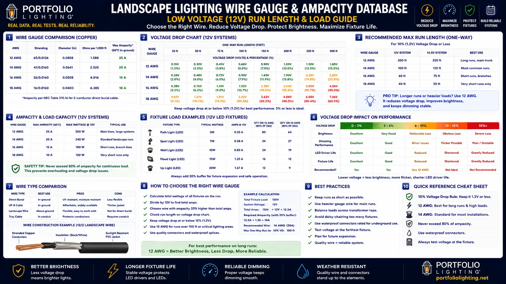
AWG Explained: Why Bigger Numbers Mean Thinner Wire
The American Wire Gauge (AWG) system is counterintuitive for most homeowners: lower AWG numbers mean thicker wire with higher capacity. 10AWG is a larger, heavier wire than 12AWG, which is larger than 14AWG. The numbering system originates from the number of drawing dies the wire was pulled through during manufacture — more draws produced thinner wire and a higher number.
For landscape lighting, the practical AWG range runs from 10 (the thickest commonly specified for residential low-voltage runs) to 16 (the thinnest that should be considered, and then only for very short, light-duty runs). Many entry-level landscape lighting kits include 18AWG wire — which is genuinely too thin for outdoor buried landscape use and should be replaced before installation.
The four dimensions that determine which AWG you need for a specific landscape lighting run are: the total wattage load on the run, the one-way run length from the transformer to the most distant fixture, the transformer output voltage (most residential systems are 12V), and the maximum acceptable voltage drop — the difference in voltage between the transformer terminals and the fixture receiving the lowest voltage on the run. Understanding all four simultaneously is what the decision matrix in this guide provides.
For a complete overview of how wire gauge interacts with the full 12V landscape system — transformer sizing, zone planning, and connector selection — see the Landscape Lighting Cable Guide and the How to Wire Landscape Lighting guide.
Ampacity Scale: 10AWG Through 16AWG for Buried 12V Landscape Applications
Ampacity is the maximum continuous current a wire can carry without exceeding its thermal rating. In direct-burial outdoor landscape applications, the ampacity values below apply for 12V copper conductor wire rated for direct burial (USE-2 or similar). Note that voltage drop — not ampacity — is the binding constraint for landscape lighting in almost every residential installation.
AWG
AWG
AWG
AWG
AWG
The Three Variables That Determine Your Wire Gauge
Every wire gauge decision for landscape lighting is determined by three variables working together. Getting one right but ignoring the others produces the same result as getting all three wrong: dim fixtures, color-shifted LEDs, and premature driver failure. The decision matrix in the next section handles all three simultaneously, but understanding what each variable contributes helps you use the matrix correctly.
Variable 1 — Total Wattage Load on the Run
Total wattage is the sum of all fixture wattages connected to a single wire run from the transformer. A run carrying eight 5W path lights carries 40W. A run carrying four 12W spotlights carries 48W. The critical mistake is planning load based on existing fixtures without leaving headroom for future additions — when the next homeowner adds three more path lights to an already borderline wire run, the last fixtures on the run go noticeably dim. Plan for at least 20% load headroom above your installed load when selecting wire gauge.
For transformer load planning that works with wire gauge decisions, see the Landscape Lighting Transformer Guide and the Portfolio Transformer Sizing Guide.
Variable 2 — One-Way Run Length
Run length is the distance from the transformer terminals to the most distant fixture on the run — measured along the wire path, not in a straight line. Voltage drop in a wire is proportional to both current (watts ÷ volts = amps) and wire length. A 100-foot run carrying 50W loses the same voltage as a 200-foot run carrying 25W — the product of amps × feet determines voltage drop, not either factor independently. This is why run length must always be considered alongside load, never in isolation.
The Landscape Lighting Voltage Drop guide and the Voltage Drop Calculator both handle the run length calculation with interactive inputs if you want to verify specific run configurations.
Variable 3 — Acceptable Voltage Drop
Voltage drop tolerance is how much voltage reduction between the transformer output and the last fixture you are willing to accept before the performance impact becomes unacceptable. For 12V LED landscape lighting, the practical tolerance is 0.5V — meaning the last fixture on the run should receive no less than 11.5V when the transformer is set to 12V. Below 11.5V, LED brightness drops measurably. Below 10.8V, color temperature shifts toward blue as LED drive current falls below design specification. Below 10.0V, driver thermal stress begins shortening fixture life. See the Voltage Drop Fixture Impact Guide for the complete thermal and performance degradation data below these voltage thresholds.
Complete Wire Gauge Decision Matrix: Load × Run Length → Correct AWG
This matrix gives you the correct wire gauge for any combination of total run wattage and one-way run length for a 12V landscape lighting system targeting a maximum 0.5V voltage drop (minimum 11.5V at the last fixture). Green cells indicate the gauge works comfortably within the 0.5V drop limit. Yellow cells indicate the gauge is at or near the limit — acceptable but with no headroom for future expansion. Red cells indicate unacceptable voltage drop — step up to the next gauge.
✓ = within 0.5V drop limit with comfortable headroom | ⚠ = at or near the 0.5V limit — no expansion headroom | ✗12 = 12AWG exceeds 0.5V drop limit, use 10AWG | "Split zones" = load and run length require zone splitting, not wire upgrade
Voltage Drop Explained: What the Numbers Mean at the Fixture
Voltage drop is not an abstract electrical concept — it has specific, measurable effects on fixture performance that change what your landscape looks like at night. Understanding what each voltage range produces at the fixture level makes wire gauge decisions concrete rather than theoretical.
Why Voltage Drop Causes LED Color Shift
A common symptom of undersized wire gauge is landscape fixtures that appear slightly blue compared to how they looked when new. This is not the LED degrading — it is an LED drive current effect. LED chips are designed to produce their rated color temperature (typically 2700K or 3000K warm white) at a specific forward current. When supply voltage drops below the LED driver's regulation threshold, the driver can no longer maintain rated forward current and begins operating in an underdriven mode where the LED's dominant wavelength shifts toward shorter wavelengths — appearing cooler and bluer. Correcting the wire gauge restores the rated drive current and the intended warm color temperature immediately.
The complete thermal and performance relationship between voltage, driver temperature, and LED service life is documented in the Voltage Drop Fixture Impact Guide and the LED Driver Heat Guide.
How to Measure Voltage Drop in an Existing System
The simplest field method for measuring voltage drop requires only a digital multimeter. Set the multimeter to DC voltage. Measure voltage at the transformer output terminals — this is your source voltage. Then measure voltage at the connector or wire terminals at the most distant fixture on the run while the system is energized under full load. The difference between the two readings is your actual voltage drop. If it exceeds 0.5V, the run needs a wire upgrade, zone split, or tap adjustment. Repeat this measurement at each zone output after any significant load addition. The How to Test a Landscape Lighting Transformer guide covers the multimeter procedure in detail.
Daisy Chain vs T-Method vs Hub Wiring: How Topology Affects Wire Gauge Requirements
The way you connect fixtures to your wire run determines the effective voltage each fixture receives — independently of what gauge wire you use. Understanding wiring topology is what allows you to use 12AWG wire where a naive daisy-chain approach would demand 10AWG.
🔗 Daisy Chain (Series Connection)
Each fixture taps off the main wire in sequence — the first fixture connects near the transformer, the second further along the same wire, and so on to the last fixture at the wire's end. Voltage at each successive fixture is lower than the previous because each fixture tap causes a small additional voltage drop. The last fixture on a daisy chain receives the lowest voltage on the entire run. Long daisy chains on small-gauge wire produce a noticeable brightness gradient — bright near the transformer, dim at the end.
Limit to 6–8 fixtures per run🔌 T-Method (Balanced Run)
Instead of one long daisy chain running to the end of a zone, the T-method runs the main wire to the center of the fixture zone and branches in two directions. Each branch carries half the total load and runs half the distance — reducing voltage drop by approximately 75% compared to a single daisy chain of the same length and total load. The T-method is the most effective technique for balancing voltage across a zone without stepping up wire gauge.
Recommended for most zones🏗 Hub Wiring (Star Topology)
A hub box is installed at or near the center of a fixture zone. A single heavy-gauge wire (typically 10AWG or 12AWG) runs from the transformer to the hub. From the hub, individual short runs (typically 14AWG or 16AWG) connect to each individual fixture. Because each fixture has its own dedicated short run from the hub, every fixture receives essentially identical voltage regardless of position. Hub wiring produces the most consistent brightness across a zone and allows individual fixture runs to use lighter gauge wire while the main trunk uses heavier gauge.
Best for large zones and premium installations🚫 Single Long Daisy Chain
A single wire run from the transformer to a distant last fixture with all zone fixtures tapped along the way. The most common installation error in DIY landscape lighting. Produces the highest voltage differential between first and last fixture of any wiring topology, requiring the heaviest gauge wire to achieve acceptable voltage balance. A long daisy chain that would require 10AWG to keep within voltage drop limits can typically be re-run as a T-method using 12AWG — with better results and less material cost.
Avoid for runs over 75 feetCommon Wiring Mistakes and Their Failure Signatures
Many landscape lighting problems that look like fixture failures are actually wire gauge, connector, or layout problems. Use these failure signatures to diagnose the system before digging up cable or replacing lights.
16AWG kit wire left installed
Most entry-level kits include 16AWG or 18AWG wire, which is often too small for the run lengths homeowners actually install. The common symptom is dim fixtures at the far end of the zone, even when the transformer is on a higher voltage tap. The stronger fix is replacing the kit wire with properly sized direct-burial cable, often 12AWG for longer runs.
Too many fixtures on one run
Adding fixtures to an existing run increases load and voltage drop for everything downstream. The clue is that lights that used to look correct become dim after new fixtures are added. The better fix is usually splitting the zone onto another transformer output or running a second cable instead of stacking more fixtures onto the same run.
Undersized or corroded fixture connectors
Snap-style pierce connectors add resistance at every fixture. On a long run with many lights, those small losses add up. If voltage looks acceptable on the main wire but low at individual fixtures, inspect the connectors for poor seating, loose contact, or green copper corrosion. See the Low Voltage Wire Connectors guide for connector selection and repair details.
Coiled extra wire buried near the fixture
Extra wire should not be buried in tight coils. A coil can make the real wire path longer than expected and may create small performance losses that do not match the planned run length. If slack is needed, leave a loose S-curve instead of a compact coil.
Wire gauges mixed in the wrong order
Heavier cable helps most when it carries power from the transformer to the first split or junction. Adding heavier wire only near the end of a run does not correct the voltage loss that already happened upstream. Use the heaviest wire on the main feed, then shorter lighter-gauge leads only where appropriate.
Wire buried too shallow
Shallow low-voltage wire is vulnerable to edging, aeration, shovel damage, animal digging, and water intrusion through nicked insulation. A common symptom is a zone that works normally when dry but trips the transformer or fails intermittently after rain. See the Landscape Lighting Wire Burial Depth Code guide before reburying or repairing cable.
NEC 2026 Class 2 Wiring Requirements for Landscape Lighting
Landscape lighting systems operating at 30V or less (virtually all residential 12V systems) are classified as Class 2 circuits under NEC 2026 Article 411. Class 2 classification significantly reduces the installation burden compared to line-voltage wiring, but specific requirements still apply.
Conductor Rating Requirements
Class 2 conductors used for landscape lighting must be rated for the environment in which they are installed. Wire buried directly in soil must be rated for direct burial — look for the USE-2 (Underground Service Entrance) or UF-B (Underground Feeder) designation on the wire jacket. Wire run above ground in conduit must be rated sunlight-resistant if exposed to UV. Never use standard indoor NM-B (Romex) wire for landscape lighting runs — it is not rated for direct burial or outdoor UV exposure regardless of conduit protection. The Landscape Lighting Cable Guide identifies the correct wire type designations for each installation context.
Burial Depth Requirements
NEC 2026 Table 300.5 specifies a minimum burial depth of 6 inches for Class 2 cables in direct burial applications. However, many state and local amendments require 12 inches — and 12 inches is the practical best practice that eliminates most mechanical damage risks from aeration, edging, and landscaping work. Always verify the local jurisdiction's requirement before installation. The Landscape Lighting Wire Burial Depth Code guide documents the most common state-level amendments to the NEC burial depth table.
Connector and Splice Requirements
All wire connections and splices in Class 2 landscape lighting circuits must be made with listed connectors rated for the environment — direct burial rated for underground connections, wet location rated for above-grade outdoor connections. The standard insulation-piercing snap connectors included with most landscape lighting kits are listed for direct burial when correctly installed. Underground wire nuts require the appropriate rated waterproof sealant filling to qualify as listed for direct burial. Dry wire nuts — even if subsequently wrapped with tape — are not listed for direct burial and create a code violation as well as a corrosion failure point. See the Low Voltage Plug and Limited Energy Connector Guide for connector selection and code compliance details.
Transformer Mounting Requirements
The transformer that drives a Class 2 landscape lighting circuit is itself a line-voltage appliance and must be installed according to NEC requirements for outdoor electrical equipment — mounted on a weather-resistant surface, maintaining clearances from combustibles, and with a listed outdoor-rated outlet supplying the primary power. See the Outdoor Lighting Transformer Mounting Code Requirements guide for the complete transformer installation code framework.
Quick-Reference Wire Gauge Specifications Table
Reference values for copper low-voltage direct-burial landscape lighting wire in a 12V system at 68°F ambient temperature. Voltage drop values are calculated for the round-trip resistance of the wire (both conductors in the two-conductor cable).
| AWG | Resistance (Ω/1000ft round trip) | Ampacity (buried) | Max Wattage at 12V | Max Run — 25W load | Max Run — 50W load | Max Run — 100W load | Best Use |
|---|---|---|---|---|---|---|---|
| 10AWG | 2.0 Ω | 30A | 360W | 290 ft | 145 ft | 72 ft | Long runs, heavy zones, main trunk lines |
| 12AWG | 3.2 Ω | 20A | 240W | 180 ft | 90 ft | 45 ft | Standard home run for most residential zones |
| 14AWG | 5.1 Ω | 15A | 180W | 113 ft | 56 ft | 28 ft | Short branch runs from hub wiring, light zones |
| 16AWG | 8.1 Ω | 13A | 156W | 71 ft | 35 ft | 17 ft | Replace existing kit wire — do not install new |
| 18AWG | 12.9 Ω | 10A | 120W | 44 ft | 22 ft | 11 ft | Indoor only — never use for landscape runs |
Maximum run lengths calculated for 0.5V maximum drop (from 12.0V to 11.5V at last fixture) at stated load. Values assume two-conductor copper direct-burial cable at 68°F. Actual performance varies with soil temperature, conductor quality, and connection resistance.
When and How to Upgrade Existing Landscape Lighting Wire
Wire gauge upgrades are one of the most impactful improvements available for existing landscape lighting systems — often restoring full fixture brightness without replacing a single fixture. Here is how to know when an upgrade is warranted and how to execute it correctly.
Signs Your Existing Wire Gauge Is Undersized
- Fixtures closer to the transformer are noticeably brighter than fixtures further away on the same run
- Adding transformer voltage tap adjustment partially improves distant fixture brightness but creates over-voltage at near fixtures
- Measured voltage at the last fixture is more than 0.5V below transformer output voltage under full load
- LED fixtures exhibit a slightly blue-shifted color temperature compared to their specification at full rated voltage
- Zone load is carried on wire that came with an entry-level landscape lighting kit (almost universally 16AWG or 18AWG)
The Upgrade Decision: Re-Pull vs T-Method vs Hub
Before digging up wire to replace it with a heavier gauge, evaluate whether a topology change would solve the problem without re-pulling. In most established landscapes, re-pulling buried wire is the most disruptive and expensive option. The T-method — installing a junction at the zone midpoint and running two shorter branches — typically solves voltage drop on long daisy chains without replacing any wire, by reducing the effective run length. Hub wiring — installing a central junction box and running short individual runs to each fixture — is the premium solution that eliminates voltage gradients entirely. Re-pulling with heavier gauge wire is the correct choice only when the run topology is already T-method or hub and the problem is the wire resistance itself rather than the topology.
Wire Upgrade Procedure for an Existing System
If re-pulling wire is the correct solution, attach the new wire to the end of the existing wire before pulling the old wire out. The existing wire acts as a fish tape through the conduit or buried path — as you pull the old wire, the new wire follows it through the same path. This works for conduit installations and for wire runs that were not buried directly without any bends or soil movement since installation. For direct-burial wire in landscaped beds, the pull-through method works less reliably — in most cases you will need to excavate along the run path to expose the wire, which can be done with a flat spade or mechanical trencher along the existing wire path.
Related Guides and Resources
- Full 2026 Hardware Benchmark Database
- Voltage Drop Fixture Impact Guide
- LED Driver Heat Guide
- IP Rating Comparison Guide
- LED Fixture Repairability Guide
- Legacy Compatibility Guide
- Landscape Lighting Cable Guide
- Landscape Lighting Wire Gauge Guide
- How to Wire Landscape Lighting
- Landscape Lighting Wiring Guide
- Landscape Lighting Voltage Drop
- Voltage Drop Calculator
- Voltage Tap Calculator
- Landscape Lighting Zones Guide
- Low Voltage Wire Connectors
- Low Voltage Plug and Connector Guide
- Landscape Lighting Transformer Guide
- Transformer Sizing Guide
- Wire Burial Depth Code Guide
- Low Voltage Permit Requirements
- Transformer Mounting Code Requirements
- Electrical Code Safety Guide
- How to Expand a Landscape Lighting System
- Terminal Blocks & Transformer Lugs
- Portfolio Landscape Lighting Wiring
- Portfolio Low Voltage Lighting Hub
- Minimizing Voltage Drop Energy Waste
Landscape Lighting Wire Gauge FAQ
What wire gauge should I use for landscape lighting?
12AWG is the recommended standard wire gauge for most residential 12V landscape lighting runs. 12AWG handles up to 100 watts at approximately 90 feet while keeping voltage drop under 0.5V (the recommended maximum for maintaining full fixture brightness in a 12V system). For shorter runs under 50 feet carrying light loads under 50 watts, 14AWG is adequate. For longer runs over 150 feet or heavy loads over 150 watts, 10AWG is required to keep voltage drop within the 0.5V limit. 16AWG — the wire included in most entry-level kits — is undersized for any run exceeding 25 feet under real-world landscape lighting loads and should be replaced with 12AWG before or during installation.
What is the maximum wattage for 12 gauge landscape wire?
12AWG low-voltage landscape wire has an ampacity (thermal capacity) of approximately 20 amps in direct-burial applications, which corresponds to 240 watts at 12V. However, the practical maximum for 12AWG in a 12V landscape lighting run is constrained by voltage drop long before ampacity becomes the limiting factor. At 90 feet of run, 12AWG supports approximately 100 watts while keeping voltage drop under 0.5V. At 150 feet, the practical maximum drops to approximately 60 watts on 12AWG. At 200 feet, 10AWG is required to carry 100 watts within the 0.5V drop limit. Size your wire for voltage drop, not ampacity — in residential 12V landscape lighting, voltage drop is always the binding constraint.
How far can I run 12 gauge landscape wire?
The maximum practical run length for 12AWG wire depends on the load. At 25 watts, 12AWG can run approximately 180 feet within the 0.5V drop limit. At 50 watts, approximately 90 feet. At 100 watts, approximately 45 feet before voltage drop becomes unacceptable. Beyond these limits, use 10AWG for the main run or split the zone into two separate runs from different transformer output terminals. The T-method — running the wire to the zone center and branching in two directions — effectively doubles the usable run length for the same wire gauge by halving the one-way run length to the most distant fixture.
What happens if landscape lighting wire gauge is too small?
Undersized wire causes voltage drop — the voltage arriving at downstream fixtures is measurably lower than the transformer output voltage. The visible symptoms are progressive: at 0.5–1.0V drop, the last fixtures on the run are noticeably dimmer than fixtures near the transformer. At 1.0–2.0V drop, LED color temperature shifts toward blue as drive current falls below design specification. Above 2.0V drop, driver thermal stress begins shortening fixture service life through the Arrhenius degradation mechanism — each 18°F rise in driver operating temperature from the additional thermal load approximately halves remaining capacitor service life. Voltage drop is the most common cause of landscape lighting performance decline in installed systems and the most commonly misdiagnosed as a transformer or fixture problem.
Can I use 16AWG wire for landscape lighting?
16AWG wire is too small for most landscape lighting home runs. Its practical voltage-drop-constrained maximum run length at a typical 50-watt zone load is only about 35 feet — far shorter than most installed landscape lighting zones. Most entry-level landscape lighting kits include 16AWG wire as the included cable, which is a significant contributor to the dim, color-shifted performance many homeowners experience with kit systems shortly after installation. Replacing kit 16AWG with 12AWG direct-burial wire is one of the highest-value upgrades available for an existing landscape lighting system — it restores full rated brightness immediately without replacing any fixtures.
What wire gauge does NEC 2026 require for landscape lighting?
NEC 2026 Article 411 governs landscape lighting systems operating at 30V or less (all residential 12V systems are Class 2 circuits under this article). The NEC does not mandate a specific minimum AWG for Class 2 landscape lighting conductors — the wire gauge decision is governed by load and voltage drop calculations, not a code minimum. The NEC does require that conductors be rated for their installation environment: direct-burial rated (USE-2 or UF-B) for underground runs, sunlight-resistant rated for UV-exposed above-ground runs. Burial depth minimums are 6 inches per NEC Table 300.5, though many local jurisdictions require 12 inches — always verify local code before installation. A licensed electrician should be consulted for installations where code compliance is in question.
Technical Data Disclaimer
Wire ampacity and voltage drop values in this guide are calculated from standard copper conductor resistance tables and NEC ampacity ratings for direct-burial Class 2 conductors at 68°F ambient. Actual performance varies with conductor quality, soil temperature, connection resistance, and installation method. All voltage drop calculations assume new wire with clean connections — actual installed systems with aged connectors may show higher effective resistance than calculated values. Consult a licensed electrician for any landscape lighting installation where load, run length, or code compliance is in question. This guide is provided for informational purposes and does not constitute engineering advice.