
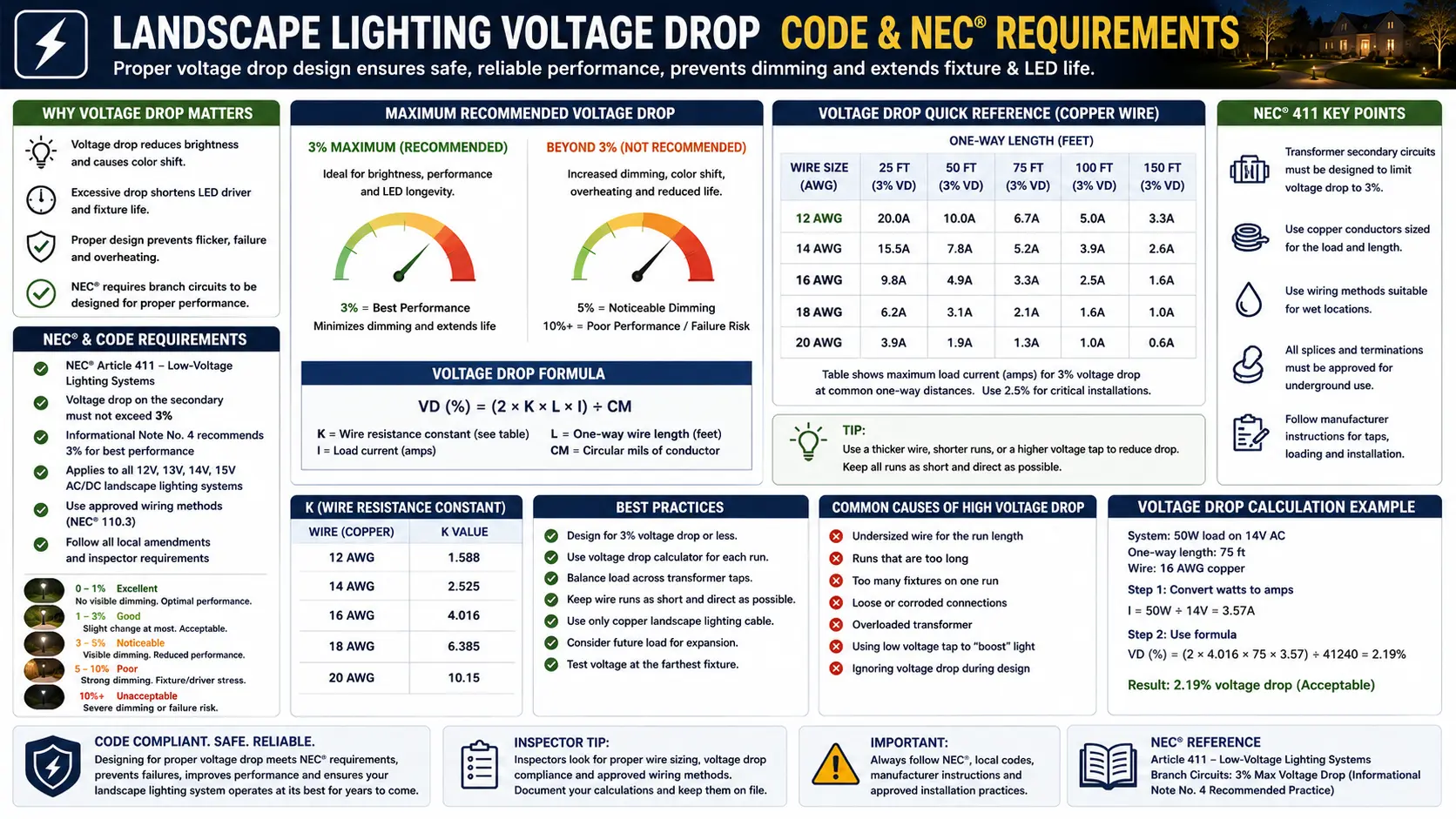
The NEC 3%/5% Voltage Drop Rule: What It Actually Is and Why It Is Not Mandatory
Before you can understand when voltage drop becomes a code requirement for landscape lighting, you need to understand the legal status of the NEC's voltage drop guidance — which is fundamentally different from what most people assume, including many electricians and inspectors.
Where the 3%/5% Rule Lives in the NEC
The NEC's voltage drop guidance appears as Informational Notes (formerly called "Fine Print Notes" or FPN) following two code sections:
"Conductors for branch circuits as defined in Article 100, sized to prevent a voltage drop exceeding 3 percent at the farthest outlet of power, heating, and lighting loads, or combinations of such loads, and where the maximum total voltage drop on both feeders and branch circuits to the farthest outlet does not exceed 5 percent, provide reasonable efficiency of operation."
This is the source of the "3% for branch circuits, 5% combined" guidance. Note the language: "provide reasonable efficiency" — not "shall" or "shall not." This is the language of a recommendation, not a requirement.
NEC 90.5(C): "Explanatory material, such as references to other standards, references to related sections of this Code, or information related to a Code rule, is included in this Code in the form of informational notes. Such notes are informational only and are not enforceable as requirements of this Code."
This is the controlling provision. NEC 90.5(C) explicitly states that Informational Notes are not enforceable requirements. An inspector who fails an installation for exceeding the 3% voltage drop recommendation is applying a guideline, not a mandatory rule — unless a local jurisdiction has specifically adopted that note as a binding requirement through an official amendment.
What "Not Enforceable" Actually Means in Practice
Several important practical implications follow from this legal status:
- An AHJ inspector cannot fail an installation solely for exceeding the 3% or 5% guideline under the NEC as published — unless local amendments have elevated the informational note to a mandatory requirement. Some inspectors do cite these notes as though they were requirements; that is technically an overreach under the NEC framework, though challenging it with an inspector is rarely practical.
- Engineering and design specifications often adopt the 3%/5% targets as project-specific requirements. On commercial or institutional projects with design specifications, these targets may be contractually enforceable even if not code-enforceable. For residential landscape lighting, they serve as a design target, not a legal threshold.
- The guidelines are good engineering practice regardless of enforceability. Exceeding 5% combined voltage drop on a 120V system produces equipment performance issues. On a 12V landscape system, exceeding equivalent percentage drops causes visible dimming, color shift, and driver malfunction. The guidance exists for good reasons — just not as enforceable code.
- Voltage drop compliance for landscape lighting usually comes from a completely different code path that has nothing to do with the 3%/5% informational notes. See the three enforcement routes below.
Three Routes That Make Voltage Drop Mandatory for Landscape Lighting
Even though the NEC's general voltage drop guidelines are informational, landscape lighting voltage drop compliance is not optional. Three separate legal mechanisms enforce voltage drop limits — each with different legal authority, different geographic scope, and different practical implications.
Here is how it applies to voltage drop: NEC Article 411 requires landscape lighting transformers to be listed (411.3 requires listed systems or listed components). Since the transformer is required to be listed, NEC 110.3(B) requires installation per the listing's instructions. Listed landscape lighting transformers and fixtures specify minimum operating voltages in their installation instructions and on their specification sheets (typically 10.8V minimum at the fixture for most consumer systems). When a wire run delivers less than the specified minimum voltage, the installation violates 110.3(B) — not because of a 3% guideline, but because the listed equipment is not being installed per its listing.
Practical enforcement: An inspector who finds voltage drop to the last fixture is below 10.8V (or whatever the listing requires) has a legitimate 110.3(B) violation to cite, regardless of whether the percentage drop exceeds 3% or 5%. The minimum voltage specification in the listing is the enforceable threshold, not a percentage.
- California: California Title 24 Part 6 (California Energy Code) includes voltage drop requirements that apply to lighting circuits. The California Electrical Code (CEC) adopts the NEC with amendments, some of which convert informational notes into binding requirements for specific applications.
- Florida: Florida Building Code Chapter 13 (Florida Building Energy Conservation Code) contains voltage drop provisions that are mandatory in Florida as state law, separate from the NEC informational notes.
- Hawaii: Hawaii has adopted NEC amendments that make voltage drop requirements more stringent, particularly in energy-related contexts.
- Other jurisdictions: Many municipalities and counties have adopted the NEC with local amendments that elevate specific informational notes to mandatory requirements. Always verify with the local AHJ.
In states with mandatory voltage drop requirements, the 3%/5% targets have legal force and inspectors can fail installations for exceeding them.
The critical difference between AHJ amendments and Route 1 (110.3(B)) is enforceability documentation. Route 1 enforcement is always available from the listing itself. Route 3 requires knowing whether your specific jurisdiction has enacted an amendment. Check with your local building department before designing or installing any landscape lighting system that may require a permit. For non-permit-required low-voltage systems, Route 1 (listing compliance) remains the primary enforcement mechanism.
See the permit requirements guide to determine whether your landscape lighting installation requires a permit in your jurisdiction.
The 12V Amplification Problem: Why Low-Voltage Systems Are Far More Sensitive
The physics of why voltage drop is so much more problematic in 12V landscape lighting than in 120V household wiring is not intuitive, but it is mathematically straightforward — and understanding it explains every practical rule of thumb in the field.
The Percentage Amplification: The Same Drop Means 10× More Impact
Voltage drop is measured as a voltage loss in absolute volts (V) but tolerated as a percentage of system voltage. The identical absolute voltage drop is 10 times more damaging as a percentage on a 12V system than on a 120V system:
The Current Amplification: Why 12V Systems Draw More Current
The second physics factor that makes 12V systems more sensitive is current. Power (P = V × I) is conserved through the transformer. For the same wattage load, lower voltage means higher current:
A 50W load at 120V draws: 50W ÷ 120V = 0.42A primary. That same 50W load at 12V draws: 50W ÷ 12V = 4.17A secondary — 10 times more current.
Voltage drop through a conductor follows Ohm's law: V = I × R. With 10 times the current flowing through the same resistance conductor, the voltage drop is 10 times greater. This is why identical wire in identical lengths produces 10× more voltage drop on the 12V secondary side than on the 120V primary side for the same wattage load. This double amplification (percentage amplification + current amplification) makes low-voltage landscape wire sizing far more critical than equivalent 120V wiring.
The LED Driver Threshold Effect: Why It's Not a Gradual Dimming
The problem is further compounded by LED driver behavior. Incandescent and halogen bulbs dim gradually as voltage drops — a 10% voltage reduction produces roughly a 10% reduction in visible brightness. LED drivers behave differently: they maintain stable light output and color temperature across a range of input voltages, then abruptly malfunction below the driver's minimum operating voltage. This creates a threshold effect: the first 8 fixtures on a daisy-chained run may appear perfectly bright at 11.5–12V, while the 9th and 10th fixtures suddenly drop to 60% brightness or fail to start because the driver's threshold has been crossed. Homeowners experiencing this "last few fixtures are dim or dark" pattern are seeing the LED driver threshold effect, not a gradual dimming curve.
I have measured voltage at every fixture on daisy-chain runs with this symptom. The pattern is consistent: fixtures 1–6 at 11.8–12.1V (fine), fixture 7 at 11.3V (noticeably dimmer), fixture 8 at 10.9V (significantly dimmer), fixture 9 at 10.4V (barely on or off). The driver threshold of most consumer LED MR16 landscape retrofits is right around 10.8–11V. The difference between a working and non-working fixture on the same run is sometimes as little as 0.5V — which corresponds to a very short additional wire length or one more fixture's current draw. This is not a marginal problem. It's a threshold problem, and it's why the voltage drop calculation matters even when "most" of the lights appear to work.
The Voltage Drop Formula for 12V Landscape Lighting Secondary Circuits
The voltage drop formula for 12V landscape lighting secondary circuits is straightforward. The challenge is applying it correctly — specifically, using round-trip wire length (both conductors carry current) and using the correct resistance values for each wire gauge.
The Formula
VD = 2 × L × I × R
Where:
VD = Voltage drop in volts (V)
L = One-way run length in feet (distance from transformer to last fixture)
I = Current in amperes = Total zone wattage (or VA for LED) ÷ 12V
R = Resistance of wire per foot (ohms/foot) — varies by gauge (see table below)
The factor of 2 accounts for the round-trip current path: current travels from the transformer through the hot conductor to the fixtures, then returns through the neutral conductor. Both conductors carry the full current and both contribute resistance. Omitting the factor of 2 produces a calculation that underestimates voltage drop by exactly 50%.
Wire Resistance Reference (Copper Conductors)
| Wire Gauge (AWG) | Resistance (Ω per foot) | Resistance (Ω per 1000 ft) | Typical Use in Landscape Lighting |
|---|---|---|---|
| 10 AWG | 0.000989 Ω/ft | 0.989 Ω/1000ft | Very long runs (>150 ft), heavy loads, main runs for large systems |
| 12 AWG | 0.001588 Ω/ft | 1.588 Ω/1000ft | Professional standard — most residential runs 50–150 ft |
| 14 AWG | 0.002525 Ω/ft | 2.525 Ω/1000ft | Short runs under 50–75 ft with light loads |
| 16 AWG | 0.004016 Ω/ft | 4.016 Ω/1000ft | Consumer kit wire — only adequate for runs under 30 ft |
| 18 AWG | 0.006385 Ω/ft | 6.385 Ω/1000ft | Fixture lead wire only — never for main landscape runs |
Using the Formula: Step by Step
- Calculate total zone current (I): Sum the VA of all fixtures on the zone run (use VA, not watts, for LED systems — see the load calculation guide for why). Divide by 12V: I = Total VA ÷ 12.
- Determine one-way run length (L): Measure the total wire length from the transformer terminals to the farthest fixture. For hub wiring, this is the hub-to-farthest-fixture distance plus transformer-to-hub distance.
- Look up wire resistance (R): Use the table above for your selected or existing wire gauge.
- Calculate voltage drop: VD = 2 × L × I × R
- Calculate delivered voltage: V_delivered = Transformer tap voltage − VD (e.g., 12V tap − VD = voltage at last fixture)
- Verify against minimum operating voltage: V_delivered ≥ fixture's minimum operating voltage from spec sheet or UL listing. Typical minimum: 10.8V for halogen; 9.5V–11V range for quality LED; 11V–11.5V for budget LED.
The Daisy-Chain Calculation Nuance: The formula above calculates voltage drop assuming all current flows to the farthest fixture — which is a worst-case approximation. In a true daisy-chain run where fixtures are evenly spaced and connected at each point, the earlier fixtures consume current before it reaches the later ones. A fully accurate calculation models the current reduction at each fixture tap-off. For practical purposes: the simpler "full current to far end" calculation is conservative (it overestimates drop) and is the appropriate approach for design — it guarantees that if the calculation shows adequate voltage, the actual system will have at least that much. If the calculation shows a marginal pass, use the more precise per-fixture model or add a larger wire gauge for margin. The voltage drop calculator handles both models.
Wire Gauge Selection Tables: Maximum Run Length by Wattage
These tables show maximum allowable one-way run lengths for each wire gauge at various load levels, targeting a maximum 1.2V drop (10% of 12V — equivalent to the difference between a 12V transformer tap and a 10.8V minimum fixture voltage). Use these tables to quickly assess whether a proposed run is feasible with a given wire gauge, then verify with the formula for your exact scenario.
| Zone Load (VA) | Current at 12V | Max Run — 10 AWG (1.2V budget) | Max Run — 12 AWG | Max Run — 14 AWG | Max Run — 16 AWG |
|---|---|---|---|---|---|
| 30 VA (6 × 5W) | 2.5A | 242 ft | 151 ft | 95 ft | 60 ft |
| 60 VA (12 × 5W or 6 × 10W) | 5.0A | 121 ft | 75 ft | 48 ft | 30 ft |
| 100 VA (10 × 10W) | 8.3A | 73 ft | 45 ft | 29 ft | 18 ft |
| 150 VA (15 × 10W) | 12.5A | 48 ft | 30 ft | 19 ft | 12 ft |
| 200 VA (20 × 10W) | 16.7A | 36 ft | 23 ft | 14 ft | 9 ft |
What This Table Tells You About 16 AWG Wire
The 16 AWG wire included in most consumer landscape lighting kit boxes from Lowe's, Home Depot, and big-box retailers is only adequate for runs of 30–60 feet with very light loads (under 30 VA). At 60 VA — a modest zone of 12 LED path lights at 5W each — 16 AWG allows only 30 feet of run before the 10% drop threshold is reached. Most residential landscape lighting installations have zones of 75–150 feet. The industry-standard minimum for most residential landscape applications is 12 AWG, and professional installers routinely default to 12 AWG regardless of run length for its combination of adequate wire life, appropriate voltage drop, and compliance with the NEC's 25-ampere secondary circuit limit for heavier loads.
When to Use 10 AWG
Ten-gauge wire becomes necessary when: (1) zone runs exceed 100 feet with loads above 60 VA, (2) a single wire run must supply more than 100 VA at any useful run length, or (3) the system uses a multi-tap transformer where higher tap voltages partially compensate for drop but 12 AWG still cannot deliver adequate voltage at full load. Ten AWG direct-burial landscape cable is available but more expensive and harder to route through confined spaces — use it where calculations confirm the need rather than as a default.
Worked Calculations: Pass, Fail, and Fix
Three complete calculations showing a passing system, a failing system, and the corrective action that brings the failing system into compliance. Each shows the full formula application and the connection to NEC 110.3(B) compliance.
Use the voltage drop calculator to verify any landscape lighting run. For transformer sizing calculations including the 80% load limit and 25-ampere secondary circuit check that must be performed alongside voltage drop, see the load calculation and code compliance guide.
Tap Voltage Compensation: When It Solves Voltage Drop and When It Creates a Hazard
Multi-tap landscape lighting transformers offer secondary output taps at 12V, 13V, 14V, and 15V. These higher taps are specifically designed for voltage drop compensation — pre-delivering a higher voltage so that after the run's drop, fixtures receive adequate operating voltage. Using them correctly is legitimate code-compliant practice. Using them incorrectly is a fire hazard.
Correct Use: Pre-Compensating for Wire Resistance
Voltage drop compensation through tap selection works by raising the starting voltage so the drop over the run still leaves fixtures within their operating range. The calculation is straightforward:
Required tap voltage = V_minimum_fixture + VD_calculated
Example: Fixture minimum 10.8V, calculated VD = 2.0V → Required tap = 10.8V + 2.0V = 12.8V → Use 13V tap.
After selecting a higher tap, verify that the first fixture on the run (which receives the full tap voltage minus only minimal drop at the very beginning of the run) does not receive voltage exceeding the fixture's maximum operating voltage. For most LED landscape fixtures, 15V is the upper limit — the maximum tap on most consumer transformers. For most halogen fixtures, maximum operating voltage is also 12–15V depending on the lamp.
When Tap Selection Becomes Dangerous
Selecting a higher tap does not fix the underlying cause of excessive voltage drop — it masks it by compensating for it. When the cause is legitimate (wire resistance over distance), tap compensation is appropriate. When the cause is a corroded splice, a loose connector, or damaged wire insulation, tap compensation is dangerous for the following reason:
A damaged or corroded connection has high resistance (much higher than clean wire per unit length). The voltage drop across this connection = I × R (Ohm's law). Raising the tap voltage from 12V to 15V does not decrease the resistance of the damaged connection — it increases the current drawn by fixtures (since more voltage is available), which increases I²R heating at the bad connection. This additional heat at a corroded splice in buried cable or at a corroded connector is a fire ignition point. The correct sequence is always: find and fix the bad connection first, then recalculate whether a higher tap is still needed for legitimate wire resistance compensation.
The multimeter delta method distinguishes them: measure voltage at the transformer terminal, then at the first fixture, then at the last fixture. For pure wire resistance drop, the voltage decreases gradually and continuously from first to last fixture. For a bad connection somewhere in the run, there will be a disproportionately large voltage drop between two specific measurement points — the drop at the connection significantly exceeds what the wire length between those points should produce. The connection-diagnostic voltage drop means fix the connection; the gradual wire-length drop means use a higher tap or heavier wire. See the complete guidance in the voltage drop guide and the load calculation guide's tap safety section.
Daisy Chain vs Hub Wiring: The Voltage Drop Comparison That Drives System Design
Wiring layout has more impact on voltage drop distribution than wire gauge selection for most residential landscape systems. Understanding why daisy-chain wiring creates uneven drop and why hub wiring equalizes it is the single most valuable system design principle for avoiding voltage drop problems.
- First fixture: ~12V (minimal drop on short first segment)
- Middle fixtures: progressively dimmer
- Last fixture: lowest voltage — often below LED minimum threshold
- Connector quality critically important — each connection adds resistance
- Easy to install — single cable from transformer to last fixture
- All fixtures receive nearly identical voltage
- Hub position optimizes run lengths (hub at centroid of fixture area)
- Main run carries full zone current — must be sized accordingly
- Individual leads carry only one fixture's current — 16 AWG adequate for short leads
- More wire and planning required; professional-preferred method
Quantifying the Hub vs Daisy-Chain Advantage
Consider 12 LED spotlights at 8 VA each (96 VA total, I = 8A) spread over a 150-foot fixture area. Transformer at one end.
- Daisy chain, 12 AWG: Last fixture at 150 ft, full zone current from transformer. VD = 2 × 150 × 8 × 0.001588 = 3.81V → Delivered = 12V - 3.81V = 8.19V. Fixtures near end fail.
- Hub at 75-ft midpoint, 12 AWG main run: Main run to hub: VD = 2 × 75 × 8 × 0.001588 = 1.91V → Hub voltage = 12V - 1.91V = 10.09V. From hub, each 12-fixture lead carries only 8 VA ÷ 12 = 0.67A for ~30 ft max: VD_lead = 2 × 30 × 0.67 × 0.001588 = 0.064V. Last fixture = 10.09V - 0.06V = 10.03V — borderline but manageable with 13V tap. All fixtures receive same voltage.
The hub eliminates the cascading drop problem at the cost of a slightly lower total hub voltage — which can be corrected with a higher tap or by positioning the hub closer to the transformer. For most landscape systems where fixtures are distributed over a 2D area (rather than a line from the transformer), hub wiring almost always produces better and more uniform results than daisy-chaining. For the complete wiring method comparison including loop wiring (a variation that further reduces drop by creating a ring circuit), see the landscape lighting wiring guide.
Related Outdoor Lighting Code and Reliability Guides
Voltage drop affects fixture performance, but fixture listing affects whether the light belongs in that environment at all. This outdoor wet-location fixture guide explains why rating labels matter before installing lights in exposed areas.
Transformer voltage taps and load balancing should be paired with safe disconnect access. This NEC transformer disconnect guide for landscape lighting explains why service access matters when voltage problems need to be tested.
Voltage-drop planning near pools should always be reviewed through a stricter safety lens. This swimming pool lighting clearance guide explains how NEC 680 can affect lighting placement and electrical separation.
Fountain lighting can be especially sensitive to voltage stability and moisture exposure. This submersible fountain lighting requirements guide explains the special concerns around underwater low-voltage lighting.
Voltage drop can create dim pathways, which may become a visibility and accessibility issue. This ADA outdoor pathway lighting guide explains why even illumination is important along routes people actually use.
Bad splices are one of the most common hidden causes of voltage loss. This landscape lighting splice connection guide explains how improper joints create resistance, corrosion, and long-term system failure.
Voltage Drop Code & NEC Requirements FAQ
Can an inspector fail my landscape lighting installation for voltage drop exceeding 3%?
Under the NEC as published, the answer is technically no — the 3%/5% voltage drop guidance appears in informational notes per NEC 90.5(C), which explicitly states they are not enforceable requirements. However, several important exceptions apply: (1) If your state has adopted energy code amendments making voltage drop mandatory (California, Florida, Hawaii), inspectors can enforce it. (2) If your local AHJ has adopted the informational notes as mandatory through a formal amendment, they are enforceable in your jurisdiction. (3) Most importantly, if the delivered voltage at the last fixture is below the transformer's or fixture's listed minimum operating voltage, the inspector can cite NEC 110.3(B) for non-compliance with the listing — which is a mandatory code provision. In practice, many inspectors cite the 3%/5% rule as though it were mandatory code; technically challenging this in the field is rarely worth the resulting friction. Designing to the 10.8V minimum at the farthest fixture satisfies all three enforcement mechanisms.
My landscape lighting uses 16 AWG wire from the kit box. Is this a code violation?
Not automatically, but probably practically. 16 AWG wire is only adequate for runs under approximately 30–60 feet with light loads (under 30 VA). Most residential landscape lighting zone runs are 75–150 feet with loads of 50–150 VA. On a 100-foot run with 10 fixtures at 7W each (70 VA at unity PF, or 100 VA accounting for LED power factor): VD = 2 × 100 × (100÷12) × 0.004016 = 6.69V. Delivered voltage = 12V - 6.69V = 5.31V. This is well below any fixture's minimum operating voltage — the fixtures won't operate, and the installation is a 110.3(B) violation. The 16 AWG wire in consumer kits is sized for the short runs typical in demo installations and small patios, not for typical landscape zone runs. Upgrade to 12 AWG for any run over 50 feet. See the wire gauge guide.
Why do some LED landscape fixtures have very wide voltage tolerances (9.5V–22V) while others require 11.5V minimum?
The voltage tolerance of an LED landscape fixture is determined by the design of its internal LED driver. A driver with a wide input voltage range (e.g., 9.5V–22V, covering both 12V AC and 24V DC systems) includes a more sophisticated power conditioning circuit — typically a constant-current driver with a wide input voltage range that maintains stable LED output across a wide supply voltage. These are more expensive to manufacture but dramatically reduce field performance issues from voltage drop. Budget LED MR16 replacements use minimal driver circuits with narrow tolerances (often 11V–13V range). Professional landscape LED fixtures from quality manufacturers specify and often guarantee minimum operating voltage in their documentation, which is the UL listing-referenced specification that NEC 110.3(B) enforces. When comparing fixtures, the minimum operating voltage specification is a quality indicator — wider tolerances reflect better driver design and better drop tolerance.
My landscape lights dim when multiple fixtures turn on simultaneously. Is this voltage drop?
Almost certainly yes — and it is a specific variant of voltage drop called transient voltage drop (or "inrush drop"). When all fixtures on a zone energize simultaneously, the total instantaneous current draw is briefly higher than the steady-state load as LED drivers "inrush" (draw higher current while initializing). This transient high current causes a brief voltage sag that may dim some or all fixtures. Once all drivers are initialized, the load settles to steady-state and the voltage recovers. In severe cases, some fixtures may fail to start (driver's startup threshold exceeded) while others immediately recover. The solution is the same as for steady-state voltage drop: heavier wire, hub wiring, shorter runs, or a higher transformer tap. Spreading fixtures across multiple independently-powered zones (multi-zone transformer) is also effective for this problem since the inrush per zone is reduced. See the landscape lights work sometimes guide for additional transient and intermittent drop causes.
If I use a 15V transformer tap, do I still need to calculate voltage drop?
Yes — the 15V tap raises the starting point but the physics of voltage drop remain identical. The delivered voltage at the last fixture is still: 15V - VD_calculated. The 15V tap extends the functional range by 3V compared to the 12V tap, allowing longer runs and heavier loads before the fixture minimum voltage is reached. But it does not eliminate voltage drop — it compensates for it. You must still calculate: Is 15V - VD_calculated ≥ fixture minimum voltage? Additionally, verify that 15V at the transformer terminal does not deliver excessive voltage to the first (closest) fixtures on the run. If the first fixture sees 14.8V (virtually the full tap voltage due to minimal drop on the short first segment) and that fixture's maximum operating voltage is 14V or 15V, you may be at or near its maximum. Use the voltage drop calculator to verify both first and last fixture voltages when using high tap settings.
Related Code Compliance and Technical Guides
- Electrical Code Safety Guide
- Load Calculation & Code Compliance
- GFCI Requirements NEC 2026
- NEC 2026 Landscape Lighting Updates
- Permit Requirements Guide
- Grounding and Bonding Guide
- Arc Fault & GFCI Code Requirements
- Wire Burial Depth Code
- Junction Box Requirements
- Transformer Mounting Code
- Contractor Licensing Requirements
- Voltage Drop Guide
- Voltage Drop Calculator
- Wire Gauge Guide
- How to Wire Landscape Lighting
- Connectors Guide
- Transformer Sizing Guide
- Transformer Size Calculator
- Hampton Bay Transformer Guide
- One Zone Not Working Guide
- Lights Work Sometimes Guide
- Landscape Lighting Maintenance