
Quick Identification Check Before Using This Manual
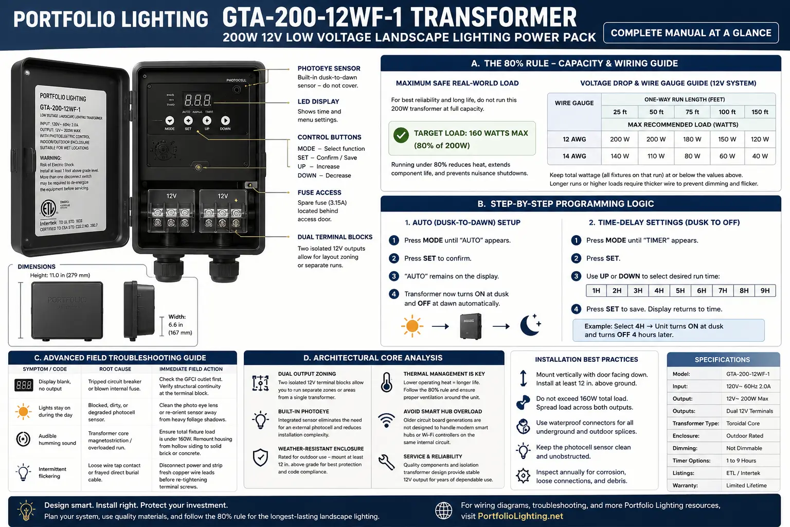
Verify the label before following any programming sequence. Portfolio used similar housings across several 200-watt power packs, but button labels, photocell behavior and terminal arrangements can vary by production run.
Look for GLA-200-12WF-1 on the side label, inside the front door or near the wiring compartment. Also record the input voltage, output voltage, wattage and any Lowe’s item number.
Public documentation for this exact suffix is limited, so this guide does not pretend every production variation used an identical control board. The load, wiring, photocell and troubleshooting guidance below applies to the 200-watt platform and should be checked against your nameplate.
GLA-200-12WF-1 Working Specifications
The 200-watt rating is the maximum nameplate capacity, not the ideal continuous target.
The 80 Percent Rule: Why 160 Watts Is the Real Target
A 200-watt transformer should normally be designed around a maximum connected load of about 160 watts.
The remaining 40 watts provides margin for heat, voltage drop, lamp tolerance, startup behavior, aging connections and future additions.
Calculation: 200 watts × 0.80 = 160 watts. A 172-watt system may still operate, but it is no longer inside the preferred long-life range.
Why full loading shortens life
Winding temperature rises as load increases. Heat also affects the timer board, photocell electronics, insulation and terminal block. A unit loaded to 200 watts is especially vulnerable after absorbing summer heat all day.
LED conversions still require calculation
Count actual labeled watts, not incandescent-equivalent brightness. Integrated LED drivers may also have startup behavior not obvious from wattage alone.
| Example | Count | Watts Each | Total | Assessment |
|---|---|---|---|---|
| LED path lights | 12 | 4W | 48W | Excellent margin |
| Mixed LEDs | 16 | 6W | 96W | Comfortable |
| High-output LEDs | 20 | 8W | 160W | Preferred ceiling |
| Legacy halogen | 10 | 20W | 200W | Too close to maximum |
Use the transformer sizing guide and wattage guide for larger systems.
The commonly recommended 80% loading guideline is supported by measured transformer performance. As magnetic transformers approach full capacity, copper losses and operating temperatures increase while efficiency gradually declines. See our Landscape Transformer Efficiency & Load Loss Benchmarks for comparative testing showing how transformer efficiency changes at 25%, 50%, 75%, and full-rated load.
Programming the GLA-200-12WF-1 Control Logic
The exact button names may differ, but the operating logic generally falls into manual on, manual off, dusk-to-dawn and dusk plus a timed number of hours.
Manual test mode
- Plug into a known-working GFCI-protected outdoor receptacle.
- Confirm output wires are secure and no bare copper bridges the terminals.
- Select manual ON or TEST.
- Verify the lights before programming the sensor.
Auto dusk-to-dawn
- Clean the photocell lens and expose it to natural daylight.
- Select AUTO, DUSK-DAWN or the photocell symbol.
- Cover the sensor only briefly for testing.
- Wait through the built-in delay.
- Uncover the sensor and confirm the lights shut off after the delay.
Dusk plus 1-to-9 hours
- Select the timed photocell mode.
- Use the hour or arrow button to choose 1 through 9 hours.
- Confirm the number in the display.
- Leave the photocell exposed to natural dusk.
- Verify operation the next evening.
After a long outage or GFCI trip, recheck the stored mode because older boards may lose settings.
Wire Gauge and Voltage Drop Guide
Correct voltage at the transformer does not prove correct voltage at the last fixture.
| Gauge | Best Use | Practical Application | Risk |
|---|---|---|---|
| 16/2 | Very short, low-load branches | Small LED runs | High drop as load rises |
| 14/2 | Short-to-medium branches | Modest LED zones | Acceptable when load is low |
| 12/2 | Primary trunk cable | Preferred general choice | Good voltage control |
| 10/2 | Long or heavy trunk | Long feed to a hub | Excellent electrically; connector sizing matters |
Use 12-gauge cable for longer runs, heavier zones or any branch already showing dimming. Use 14-gauge for shorter LED branches with modest load.
A larger transformer does not reduce cable resistance. Split the zone, use heavier wire or repair bad connections.
Use the voltage drop calculator, wire gauge guide and zone guide.
Terminal Connection Procedure
- Unplug the transformer and verify the display is off.
- Cut away corroded or crushed wire ends.
- Strip to clean, bright copper.
- Insert the conductor fully under the clamp.
- Tighten firmly without stripping the screw.
- Tug each conductor and keep bare copper separated.
Advanced Field Troubleshooting Matrix
| Symptom | Likely Cause | Immediate Action | Do Not Assume |
|---|---|---|---|
| Blank display, no output | Dead receptacle, GFCI, breaker, cord, internal protection or board | Test outlet, reset GFCI, inspect cord | Transformer failure before outlet verification |
| Lights on in daylight | Dirty, blocked, shaded or failed photocell | Clean and expose sensor | Timer failure first |
| No automatic start | Artificial light, wrong mode, failed sensor or lost setting | Cover sensor, confirm mode, wait through delay | Instant sensor response |
| Loud hum | Overload, loose mounting, aging core or poor terminals | Reduce below 160W and tighten mounting | Every hum means failure |
| Flickering | Loose terminal, corroded connector, damaged cable or voltage drop | Strip fresh copper and measure first/last fixture voltage | All lamps are bad |
| Very hot housing | Overload, blocked airflow, ambient heat or loose connection | Measure load and clear ventilation | Heat is normal at any level |
| One zone dim | Branch drop, damaged cable or bad splice | Measure terminal, midpoint and endpoint voltage | Larger transformer fixes the cable |
| GFCI trips after rain | Wet receptacle, cord, cable or fixture | Unplug, dry and isolate branches | Repeated resetting is safe |
Why the Transformer Hums
A faint steady hum is common in magnetic transformers. Concern increases when it becomes louder, changes to a harsh buzz, appears with flicker or is accompanied by excessive heat.
Hollow siding can amplify normal vibration. Solid masonry usually resonates less.
After unplugging, disconnect the low-voltage output and briefly compare no-load sound. If buzzing drops sharply, the connected load or wiring is contributing.
See the transformer buzzing guide and overheating guide.
Photocell Diagnosis
The photocell needs a clear view of daylight. Foliage, overhangs, dirt or paint can make it believe it is nighttime.
Lights stay on all day
Clean the lens and remove shadow. If the lights shut off after the delay, the sensor is working.
Lights cycle on and off
The sensor may see light from the fixtures. Reorient or shield it from direct fixture light while preserving its view of the sky.
Lights never turn on in AUTO
Cover the photocell completely. If manual mode works but covered AUTO does not respond after the delay, the sensor or board may have failed.
Use the photocell troubleshooting guide and replacement guide.
Architectural Core Analysis
The GLA-200-12WF-1 is useful because it combines substantial residential capacity, simple photocell/timer control and a serviceable terminal area.
The magnetic core is often not the first part to fail. Heat, photocell aging, control-board trouble, corroded terminals and overloaded wiring usually appear first.
Separate branch runs can be used for practical zoning instead of forcing every fixture onto one long daisy chain.
Older boards were not designed around repeated smart-plug cycling. External automation can cause lost settings or confusing behavior.
Repair or Replace?
| Condition | Repair Makes Sense | Replace When |
|---|---|---|
| Dirty photocell | Clean and reposition | Sensor will not respond |
| Corroded wire ends | Cut back and reconnect | Terminal block is burned |
| Lost setting | Reprogram | Settings will not hold |
| Stripped terminal screw | Replace terminal if serviceable | Block is cracked or charred |
| Loud buzz and heat | Correct load and mounting | Noise remains with no load |
| Burn smell or melted insulation | No | Replace immediately |
| No output with verified input | Qualified internal repair only | Usually practical for homeowners |
See the replacement guide, alternatives guide and replacement instructions.
GLA-200-12WF-1 FAQ
Can I use all 200 watts?
Use 160 watts as the preferred continuous design ceiling.
Can I use LEDs?
Usually yes, when they are designed for 12-volt AC landscape lighting.
Why is the last light dim?
Usually cable voltage drop or a high-resistance connection.
Why do lights stay on in daylight?
The photocell may be dirty, shaded, blocked or failing.
Should I replace it if the timer fails?
Not always. Manual output plus an external listed outdoor control can be a practical workaround.

Lighting specialist focused on Portfolio transformer troubleshooting, voltage drop, photocell failures, terminals and replacement compatibility.