
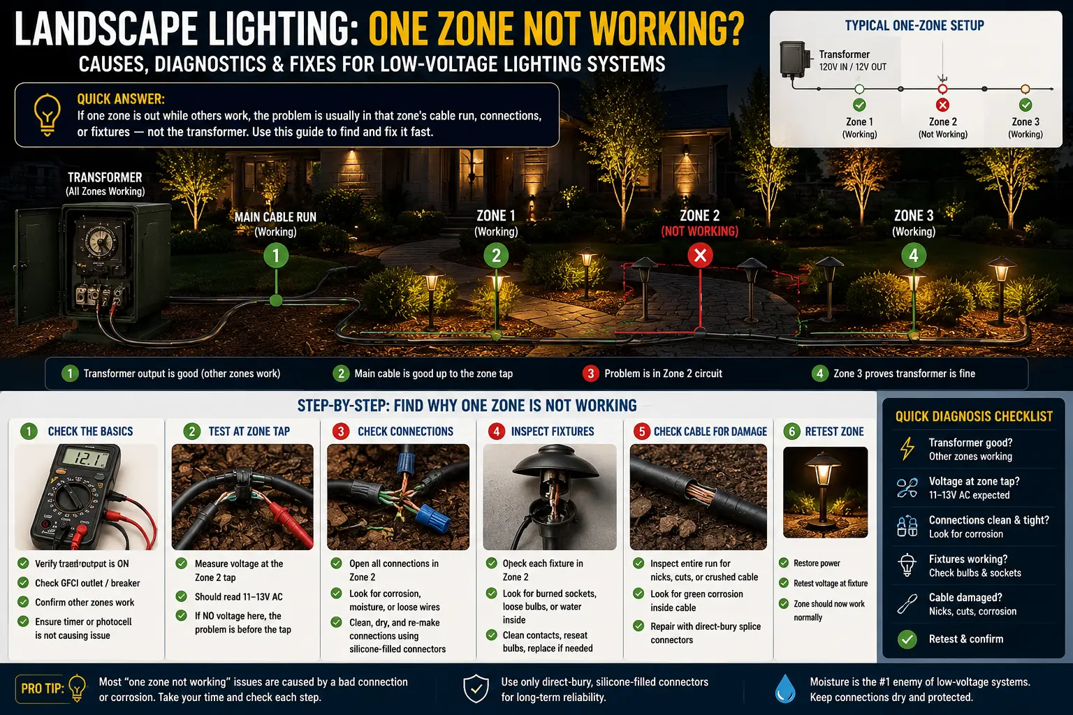
All Root Causes: Every Reason One Zone Goes Dead
A single dead zone while others work narrows the cause to a short, defined list. Every possible cause falls into one of six categories. The diagnostic steps below work through these in order of how quickly each can be confirmed or eliminated, from the fastest (30-second timer check) to the most involved (tracing and repairing a buried wire break).
A single lighting zone that suddenly stops working may actually be tied to a transformer protection event, overloaded tap or internal fault condition instead of a failed fixture. This transformer error code reference for landscape lighting systems helps explain how different transformers report zone faults, overload warnings and wiring-related shutdown behavior.
| Symptom Variation | Most Likely Cause | First Check |
|---|---|---|
| Zone has never worked since a power outage | Zone schedule reset to OFF or wrong time | Multi-zone transformer zone settings |
| Zone stopped working overnight, no recent yard work | Per-zone breaker tripped, or connector corroded | Per-zone breaker on transformer face |
| Zone stopped working after recent digging, edging, or aeration | Cut or shorted wire on zone run | Visual walk of the zone's wire path |
| Zone stops working after rain, then sometimes comes back | Water in fixture socket or wet buried splice creating intermittent short | Inspect fixtures and buried wire nut connections |
| Zone breaker trips immediately when reset | Active short still present — wire damage or shorted fixture | Disconnect all fixtures on run, reconnect one at a time |
| Zone breaker holds but no lights come on | Open circuit — wire break, disconnected terminal, or failed connector | Multimeter test at transformer terminal and first fixture |
| Zone works sometimes, randomly cuts out | Loose terminal connection or borderline wire short (intermittent) | Re-tighten transformer terminal screws, inspect recent splice points |
| Only the last few fixtures on a zone are dead | Not a zone problem — this is a broken connection mid-run. See voltage drop / cut wire mid-run | Test voltage at last working fixture vs first dead fixture |
Quick Checks First: No Tools Required
Before reaching for a multimeter, run through these checks. Two of the most common causes — a zone schedule setting and a per-zone breaker button — can be confirmed and fixed in under three minutes without any tools.
Transformer Terminal Test: Exact Multimeter Readings for Every Scenario
If quick checks did not restore the zone, the next step is a multimeter voltage measurement at the transformer's output terminals. This test takes under five minutes and definitively tells you whether the problem is inside the transformer or out in the wire run. You need: a digital multimeter ($15–$30 at any hardware store), with the selector set to AC voltage (VAC or V~) on the 20V range.
How to Test
With the transformer powered ON and set to manual ON for the dead zone, open the transformer cabinet. Locate the terminal posts — typically labeled COM (or Common) and one or more voltage taps (12V, 13V, 14V, 15V). The dead zone's wire is connected to one voltage tap and one COM post. Touch one multimeter probe to the COM terminal and the other probe to the voltage terminal where the dead zone's wire is attached. Make contact directly with the metal terminal post or screw head — not the wire insulation.
Testing with No Wires Attached to the Terminal
For the most definitive test of the transformer's zone output, disconnect the dead zone's wire from the terminal first. With no load connected, the terminal should read 12–15V (the transformer's nominal output). If you get 0V even with no wires attached, the zone output has failed internally. If you get 12–15V with wires disconnected but 0V with the wire run connected, the wire run has a dead short — when connected, it collapses the output voltage to zero. A short is confirmed.
Per-Zone Internal Breaker: Finding, Resetting, and Diagnosing
Many landscape transformers — particularly those marketed for multi-zone use — include individual circuit protection for each zone output. Understanding how this protection works, where to find the reset button, and what tripping patterns mean is the fastest route to a working zone.
How Per-Zone Circuit Protection Works
A per-zone breaker is a small circuit breaker (or occasionally a resettable fuse) wired in series with each zone's output terminal. Its job is to detect overloads — when a zone draws more current than the breaker is rated for, it opens (trips), cutting power to that zone only. The key diagnostic value of this design is that a tripped zone breaker confirms a fault exists on that zone's run — either excessive load (too many fixtures or a shorted fixture pulling overcurrent) or a direct short in the wire.
Per-zone breakers are found on: higher-end consumer transformers (Hampton Bay 200W Hubspace, SUNVIE dual-zone, multi-zone professional transformers), professional-grade transformers (FX Luminaire, Kichler), and some mid-range units. Basic consumer transformers (older Malibu, Portfolio, Hampton Bay SL-120) typically have a single master internal breaker rather than per-zone breakers.
Locating the Per-Zone Reset Button
Open the transformer cabinet. Look for small round or rectangular buttons adjacent to the terminal block, typically near the screw terminals where zone wires are attached. The button for the tripped zone will appear extended or popped out — physically different from buttons on working zones. On some transformers, the per-zone protection is labeled on the transformer face. On others, you need to consult the transformer manual. For Hampton Bay transformers, see the Hampton Bay transformer guide.
What the Tripping Pattern Tells You
| Tripping Pattern | What It Means | Next Action |
|---|---|---|
| Trips immediately upon reset (within 1–2 seconds) | Dead short on the zone's wire run — two conductors touching directly. High current draw exceeds breaker rating instantly. | Disconnect all fixtures from the zone's run. Reconnect the bare wire (no fixtures) and reset. If it holds, add fixtures one at a time to find the shorted fixture. If it still trips with no fixtures, the wire itself is shorted. |
| Trips after 2–10 minutes of operation | Overload — total fixture wattage on the zone exceeds the breaker's rated capacity, and the breaker heats up over time. Or a marginally wet connection that becomes conductive as current flows. | Calculate total wattage on the zone. If over the rated zone capacity (often 150W or 300W per zone — check transformer spec), remove fixtures. Also inspect all connectors for moisture ingress. |
| Trips after rain events but not during dry periods | Ground fault from moisture entering a fixture socket, buried splice, or connector. Water creates a conductive path between the two conductors. | Inspect all connectors and fixture sockets for water intrusion. Look for connectors sitting in wet soil. Replace any non-waterproof splices with silicone-filled direct-burial wire nuts. |
| Resets and holds, zone works normally | Transient overload — may have been a temporary short (squirrel chew that self-cleared, connector that dried out after rain). Zone is functioning. | Monitor for recurrence. If it trips again within a few days, investigate for the underlying cause. Check all connectors. |
Wire Fault Isolation: Finding the Break or Short on a Dead Zone
If the transformer terminal reads 12–15V (confirmed working output) but no fixtures light up, or if the per-zone breaker trips and holds no load, the fault is somewhere on the wire run between the transformer and the first fixture. Here is the complete systematic procedure to locate it without digging up the entire zone.
One dead lighting zone is very different from a total system outage affecting every fixture in the yard. Our landscape lighting all-lights-out diagnostic guide explains how to separate localized branch failures from transformer shutdowns, shared electrical interruptions, timer failures, and main-feed cable problems that disable the entire system.
Step 1: Establish Whether the Fault Is an Open Circuit or a Short Circuit
These require different diagnostic approaches. With the transformer powered off and the zone's wires disconnected from the terminal:
- Open circuit test: Set your multimeter to continuity or resistance mode. Touch one probe to each conductor of the zone's wire at the transformer end. Walk the wire and test at each fixture connector along the run. An open circuit shows infinite resistance (or "OL" on the display) — meaning the conductor has a break somewhere. A working run shows a low resistance (a few ohms, depending on wire length and gauge).
- Short circuit test: Still at the transformer end with wires disconnected, touch one probe to each conductor. A short reads near 0 ohms — both conductors are touching somewhere. A healthy run shows high resistance (megaohms or "OL") between the two conductors when no fixtures are connected.
Step 2: The Half-Run Method — Pinpointing the Fault Without Extensive Digging
The fastest way to locate an underground wire break without a wire locator tool is the binary search (half-run) method. It minimizes digging to the smallest possible section.
Using a Wire Locator / Tone Generator for Non-Destructive Location
A wire locator (also called a wire path tracer or tone generator) sends a signal through the landscape wire that can be detected with a handheld receiver above ground, showing the wire's path and identifying where signal loss occurs — which is where the break is. Professional-grade units cost $150–$300. Consumer-grade low-voltage wire locators start at $50–$80 and are sufficient for most residential troubleshooting. Kichler's professional troubleshooting guide specifically lists a cable fault locator as essential for finding buried wire breaks.
Without a wire locator, the visual clues discussed below — combined with the half-run method — are sufficient in most cases, particularly when recent yard work has occurred in a specific area.
Where Wire Breaks Most Often Occur
- Within 12 inches of lawn edging blade cuts: Edging tools run parallel to bed borders and frequently slice through landscape wire at or just below the soil surface. Walk every edging line within 6 feet of the wire path.
- At aeration holes: Lawn aerators punch hollow tines 2–4 inches deep at 3–4 inch spacing across the entire lawn. If aeration has been done recently on a lawn that landscape wire crosses, check systematically along the entire crossing path.
- Where the wire exits the transformer cabinet: This is a high-stress bend point. The wire flexes every time the transformer cabinet is opened or adjusted. Internally, the wire can crack while appearing intact externally.
- At tree and shrub root lines: Root growth exerts slow but enormous pressure on buried wire. A wire that was fine two seasons ago can be crushed or cut by root growth over the winter.
- At shallow crossing points: Landscape wire crossing a driveway, sidewalk, or patio edge is often installed in a shallow sleeve or run under just a thin layer of mulch — these points are vulnerable to frost heaving and surface traffic.
- At any previously-repaired or non-waterproof splice: Standard electrical tape and basic wire nuts fail underground. If the system has any previously repaired areas that used tape or standard wire nuts, those are likely to have failed and should be replaced with silicone-filled direct-burial connectors.
In my field experience, over 70% of cut-wire failures in established residential landscape lighting systems have a simple, visible cause within two feet of recent yard work. When a homeowner mentions "we had the lawn aerated last month" or "we put in some new plants near the front beds," the wire break is almost always within the disturbed zone. Walk that area carefully before pulling out the half-run method — the break is usually findable in under five minutes of looking.
Shorted Fixture Taking Down an Entire Zone: How to Find It
A single failing fixture can shut down every other fixture on its zone run — not by a cascade of power failure, but by drawing so much current that the zone's per-circuit breaker trips. This is a surprisingly common failure mode and one of the most confusing for homeowners, because the symptom (entire zone dark) looks like a wire break when the actual cause is a single bad fixture.
What Makes a Fixture Short
The most common causes of a zone-killing fixture short are water intrusion and connector failure. When water enters the fixture's socket area — usually through a failed lens gasket or a cracked housing — it bridges the gap between the socket's electrical contacts. Both conductors of the landscape wire are now connected to each other through the water in the socket, creating a near-zero-resistance path (a short). The zone's breaker sees massive current draw and trips. After the rain dries out, the short clears and the zone works again — until the next rain event. This "works when dry, fails when wet" pattern is diagnostic of a fixture short caused by water intrusion.
Connector failure at the fixture's pierce-point connection can also create a short if the connector's two contact pins migrate toward each other through corrosion or physical deformation, eventually creating a connection between the two conductors of the landscape wire.
The Fixture Isolation Procedure
- Turn off the transformer. Turn it completely off, not just to the zone schedule's off period — you need the transformer de-energized for safe handling.
- Disconnect ALL fixtures from the dead zone's run. Go to each fixture's connector box and disconnect it from the landscape wire. For pierce-point connectors, you are looking for a connector box with thumbscrews or a snap-fit lid — open it and remove the wire. For hub-wired systems, disconnect at the hub.
- Reconnect the zone's bare wire (no fixtures) to the transformer terminal and power on. If the per-zone breaker holds with no fixtures attached: the wire itself is healthy and a fixture is the cause. If it still trips with nothing attached: the wire itself has a short.
- Reconnect fixtures one at a time. After each fixture reconnection, power on and check: does the breaker hold or trip? The breaker tripping after adding a specific fixture identifies that fixture as the cause. Remove it and continue the others.
- Inspect the identified shorted fixture. Look for water in the socket area, green or white corrosion on the contacts, a cracked or missing lens gasket, or a failed connector. Clean light corrosion with fine sandpaper and allow to dry thoroughly. If the housing is cracked or the socket is visibly melted, replace the fixture. See the landscape lighting replacement parts guide for compatible replacement options.
Connector Failures at Fixtures and Transformer Terminals
Pierce-point connectors — the twist-in or thumbscrew-close connector boxes that attach each landscape fixture to the wire run without cutting the wire — are the most common site of electrical failure in low-voltage landscape lighting systems. Understanding why they fail and how to identify the failure helps distinguish them from wire breaks.
How Pierce-Point Connectors Fail
When a pierce-point connector is installed correctly, its internal teeth puncture the wire insulation and make contact with the copper conductors inside. Over time, the steel teeth and copper conductors — two dissimilar metals in a wet environment — develop galvanic corrosion at the contact point. This corrosion is electrically resistive: it does not completely break the circuit but increases resistance, causing voltage drop across the connector. As corrosion worsens, the connection can become intermittent or open entirely, taking the fixture offline. For a zone that has multiple failing connectors in sequence, the effect can be progressive dimming followed by complete loss.
A dead zone caused entirely by connector failures (rather than a wire break) is uncommon but possible in older systems where connectors were installed without waterproof protection. The pattern tends to be progressive — fixtures go dark one at a time over several seasons — rather than all at once. An all-at-once failure is more consistent with a wire break or short.
Testing a Connector for Voltage
At the first dead fixture on the zone, open the connector box (three thumbscrews or snap-fit). With the transformer on, measure voltage between the two conductors of the landscape wire at the connector point — not at the fixture's lead wire, but at the main run wire. If you get 12V at the main wire but 0V at the fixture's connector pins: the connector has failed. The wire is delivering power; the connector is not passing it through to the fixture. Replace the connector with a new waterproof pierce-point connector or a silicone-filled wire nut connecting the fixture's lead wire directly to the stripped main wire. For connector selection guidance, see the landscape lighting connectors guide.
Transformer Terminal Connector Failure
The point where the zone's wire connects to the transformer's terminal block is also a common failure point. The wire must be fully stripped (3/4 inch of insulation removed), the copper must be clean and bright (not green or oxidized), the wire must be fully inserted into the terminal opening (not just resting against it), and the terminal screw must be tightened firmly. Any deviation from these conditions creates a poor connection that degrades over time. To repair: turn off the transformer, loosen the terminal screw, pull the wire free, cut back to clean copper, strip fresh insulation, reinsert firmly, and tighten the screw. See the landscape lighting wiring guide for proper terminal connection technique.
Hub-Wired Systems: Where They Fail and How to Check
Hub-wired (or T-connection) landscape lighting systems route the main wire run to a central hub or junction box, with individual fixture lead wires branching out from the hub to each fixture. This approach reduces voltage drop compared to long daisy-chain runs but introduces a new failure point: the hub itself. A single failed connection at the hub can take down every fixture connected to that hub — exactly mimicking a zone failure.
Identifying Whether Your System Uses Hub Wiring
In a daisy-chain system, each fixture's connector box is attached directly to the main landscape wire run, and removing one fixture does not affect others downstream. In a hub system, multiple fixture lead wires converge at one point — a wire nut cluster, a commercial hub splitter, or a junction box buried at a central location. If you can find a spot where three or more wires join together (other than at the transformer), you have hub wiring at that point.
Testing a Hub Connection
Locate the hub serving the dead zone's fixtures — typically at a central point in the zone's geographic area. Look for a wire nut cluster or junction box at or slightly below ground level. Open the hub and inspect the wire nut connections. Common hub failures include: wire nuts that have backed off the conductors (spin freely by hand — a sign the conductors are not engaged), corroded wire nut contacts, and individual wires that have pulled free from the connector. With the transformer on, measure voltage at the main wire entering the hub (12V expected) and at each branch wire leaving the hub (also 12V if the connection is sound, 0V if the branch is disconnected). A 0V reading on a specific branch from a hub confirms a failed connection on that branch — not a zone-level fault. Replace failed wire nuts with silicone-filled waterproof wire nuts and ensure all conductor ends are clean and the nut is tight.
Cut Wire Repair: Complete Procedure for Buried Landscape Wire
Once the break is located, the repair is straightforward but must be done correctly — because a landscaping wire repair that uses the wrong materials will fail underground within one to two seasons. The key requirement is absolute waterproofing. Water in a buried wire splice creates a short circuit that trips breakers, causes intermittent operation, and eventually corrodes the copper until the splice fails entirely.
Tools and Materials
- Wire strippers set for 14 or 16 AWG wire (match your existing landscape wire gauge)
- Silicone-filled waterproof wire nuts — the critical component. These are also called "direct burial" wire connectors or "gel-filled wire nuts." Do NOT use standard indoor wire nuts (orange, yellow, or tan) for this repair — they are not waterproof and will fail underground. Available at hardware stores, typically in the landscape lighting or outdoor electrical section.
- Optionally: a waterproof wire splice kit or direct-burial gel-filled splicer designed specifically for low-voltage landscape wire
- Electrical tape is NOT a substitute for waterproof wire nuts in a buried application
Repair Procedure
Multi-Zone Transformer Zone Settings: Diagnosing Control-Level Zone Failures
Multi-zone transformers offer independent scheduling, voltage selection, and sometimes photocell response per zone. This flexibility creates a class of failures that looks like a dead zone but is actually a programming or control configuration issue. Here is a complete reference for every control-level zone setting that can cause one zone to be dark while others run.
Common Multi-Zone Control Configurations
| Zone Setting | What It Does | How It Can Cause a Dead Zone | Where to Check |
|---|---|---|---|
| Zone ON/OFF Schedule | Sets the timer ON time and OFF time for each zone independently | Zone programmed to wrong ON time (e.g., a daytime window), or accidentally set to ALWAYS OFF, or schedule corrupted by a power outage | Transformer display — navigate to zone-specific timer menu. Set to MANUAL ON to bypass and test. |
| Zone Dusk-to-Dawn Mode | Uses photocell input to enable/disable the zone automatically | If the photocell is dirty, covered, or defective, it may keep a specific zone in OFF state permanently. In some transformers, per-zone photocell settings override the timer. | Cover the photocell with black tape. If zone turns on, the photocell is the issue. Clean or replace the photocell. |
| Zone Voltage Tap Selection | On multi-tap transformers, each zone can be assigned to a different voltage output (12V, 13V, 14V, 15V) | Not directly a cause of a dead zone, but a zone at 12V with a heavily loaded long run may have insufficient voltage to activate LED drivers — appears dead but is actually extremely low voltage | Measure voltage at the last fixture on the zone. If below 10V, the zone is underpowered — move to a higher voltage tap. |
| Zone Manual ALWAYS-OFF Setting | Some transformers have a permanent OFF override per zone for maintenance purposes | The zone was manually turned off for servicing and the setting was never reversed | Check zone settings for any permanent OFF or disable mode. Enable or set to automatic. |
| Zone Countdown Timer | Zone runs for a set number of hours after sunset, then shuts off | Countdown set to 0 hours or a very short period means the zone shuts off almost immediately after triggering | Check countdown setting for each zone. Set to appropriate run duration (typically 4–8 hours). |
Two-Zone Transformer: The Most Common Multi-Zone Configuration
Two-zone transformers (SUNVIE 200W, Moonrays 28285 WiFi, Hampton Bay Hubspace, and various others) give each zone its own button on the transformer face and its own schedule. Zone 1 and Zone 2 are entirely independent — Zone 1 failing does not affect Zone 2 and vice versa. This independence is a debugging advantage: the working zone confirms the transformer, GFCI, and power supply are all functional. The failure is definitively in Zone 1's settings, Zone 1's terminal/breaker, or Zone 1's wire run. For two-zone transformer troubleshooting beyond what is covered here, see the transformer guide.
A lighting zone that suddenly stops working may involve more than one failure point because unstable fixtures, damaged stakes, corroded connectors and overloaded transformers often appear together in older systems. This landscape lighting broken stake repair guide explains practical ways to reinforce or replace failing fixture mounts, while this transformer warning and error code guide helps identify overload conditions, short circuits and protection shutdowns before rewiring the entire zone.
One Zone Not Working FAQ
My landscape lighting has two zones and one stopped working. What should I check first?
With a two-zone transformer where Zone 1 works and Zone 2 is dead, work through this sequence in order: (1) Set Zone 2 to manual ON to bypass the timer — if it comes on, a schedule setting was wrong. (2) Check for a per-zone breaker or reset button for Zone 2 on the transformer face — press it and test. (3) Measure voltage at Zone 2's output terminal with a multimeter (should be 11.5–15V). (4) Check Zone 2's wire connections at the transformer terminal — pull-test each wire for tightness. (5) Visually walk Zone 2's wire run for visible damage. Each step takes 2–5 minutes. Most two-zone single-dead-zone failures resolve at step 1 or 2.
Why does one zone of landscape lights work when dry but fail after rain?
Rain-induced zone failure is almost always a ground fault — water getting into an electrical connection and creating a conductive path between the two conductors of the landscape wire. The most common entry points are: unsealed or cracked fixture housings (water enters the socket area), non-waterproof wire splices buried underground (standard wire nuts that allow water wicking), and pierce-point connectors that are not fully closed and have allowed water under the connector lid. When the water dries out, the resistance rises and the circuit works again. The fix is identifying all non-waterproof connections on the zone's run and replacing them with silicone-filled direct-burial wire nuts or waterproof connectors. See the connectors guide.
Can one bad fixture shut down an entire zone?
Yes — a shorted fixture draws excessive current that trips the zone's per-circuit breaker, shutting down all other fixtures on that run. This is particularly common after rain events when water enters older fixture sockets. The diagnostic procedure: turn off the transformer, disconnect ALL fixtures from the zone, reconnect the bare wire, reset the zone's breaker, and power on. If the bare wire holds the breaker: add fixtures back one at a time until the breaker trips — that fixture is the cause. For fixture-level diagnostics, see the landscape lighting troubleshooting guide.
The zone's transformer terminal reads 12V but no fixtures light up — what is wrong?
If you measure 12V at the transformer's output terminal for the dead zone, the transformer is delivering power. The open circuit is somewhere between the terminal and the fixtures. Work through this sequence: (1) Inspect the wire connections at the terminal post — the wire may be making contact but under high resistance from corrosion. Pull the wire out, clean the copper end, reinsert, and tighten. (2) Walk to the first fixture on the zone and measure voltage at its connector box connection to the main wire. If 0V there, the wire between transformer and first fixture has a break. If 12V there but the fixture doesn't light, the fixture or its connector is failed. Continue measuring at each fixture until voltage drops to 0V — the break is between the last 12V point and the first 0V point.
How deep should I bury the replacement or repaired landscape wire?
A minimum of 4 inches deep for areas without regular soil disturbance. Six inches deep wherever the area is subject to lawn maintenance, edging, aeration, or foot traffic. Landscape wire crossing lawn areas should be at least 6 inches deep — most consumer lawn aerators punch 2–4 inches deep, but some commercial aerators reach 5–6 inches. Wire along bed borders (a very common cut location) should be buried 6–8 inches deep and routed 8–12 inches away from the edging line. Wire crossing a driveway or sidewalk should be sleeved in PVC conduit and buried at least 6 inches. For complete wiring depth and routing guidance, see the landscape lighting wiring guide.
Do I need a special wire to repair landscape lighting wire underground?
The wire itself is standard direct-burial low-voltage landscape wire — 12AWG, 14AWG, or 16AWG depending on your system's run length and load. The critical difference from indoor wire is the insulation, which must be rated for direct burial (direct contact with soil and moisture). Most landscape wire sold at hardware stores in the outdoor or landscape lighting section is appropriately rated. What most homeowners get wrong is the splice connection at the repair point: standard indoor wire nuts are not waterproof and fail underground within one to two seasons. Use silicone-filled (gel-filled) wire nuts rated for direct burial — also sold as waterproof wire connectors or direct-burial connectors in the landscape lighting section.
Related Troubleshooting and Repair Guides
- Landscape Lighting Troubleshooting Hub
- How to Test a Transformer
- Lights Work Sometimes Guide
- Timer Not Working Guide
- Voltage Drop Guide
- Voltage Drop Calculator
- Connectors Guide
- Low-Voltage Connector Guide
- How to Wire Landscape Lighting
- Wire Gauge Guide
- Landscape Lighting Maintenance
- Transformer Sizing Guide
- Transformer Size Calculator
- Hampton Bay Transformer Guide
- Replace a Transformer Guide
- Replacement Parts Guide
- LED vs Halogen Guide
- Bulb Replacement Guide
- Landscape Lighting Layout Guide
- Low-Voltage Lighting Zones Guide
- Portfolio Lighting Troubleshooting
- Brand Comparison Guide
- Landscape Lighting Cost Guide