
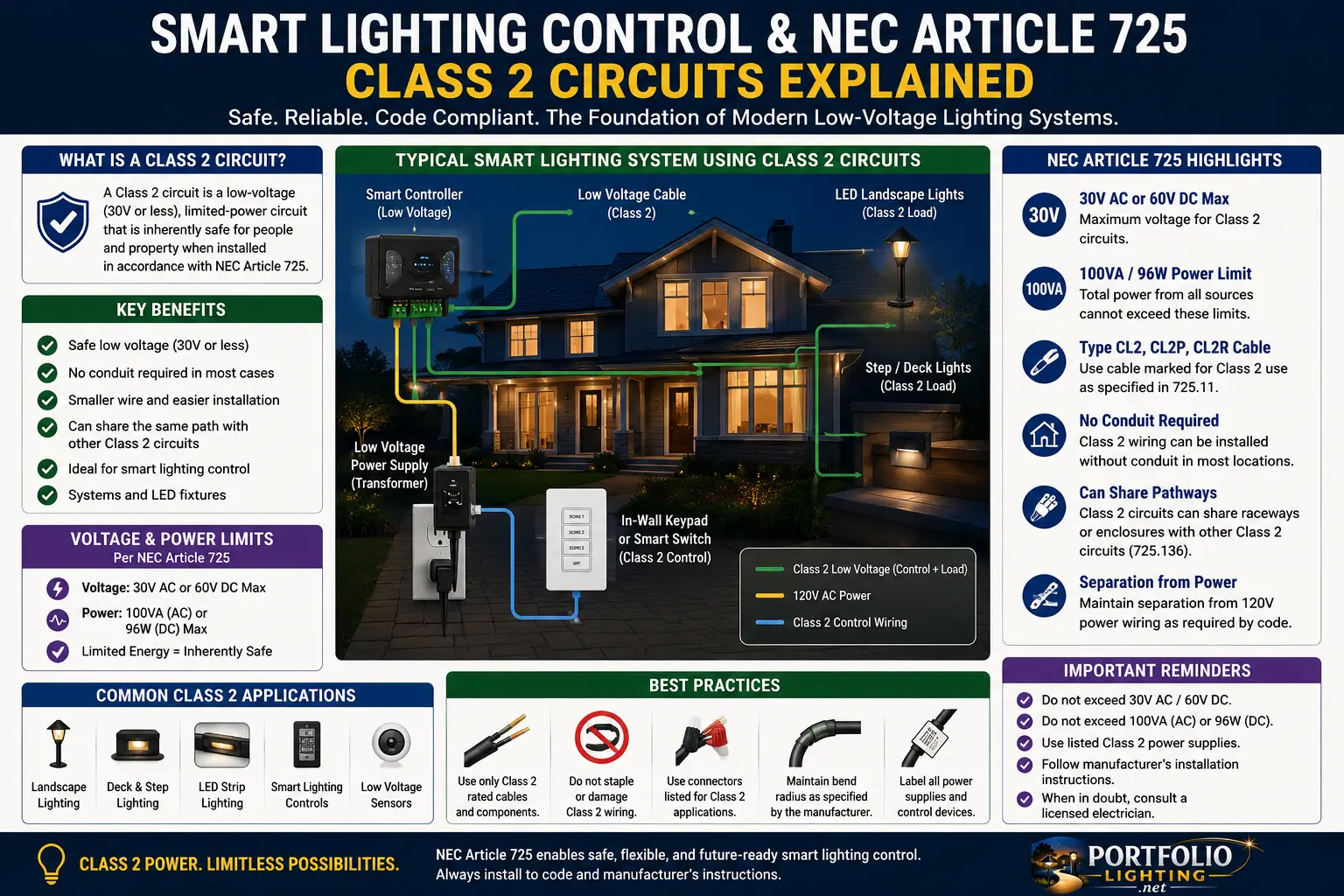
Quick Answer: What Article 725 Means for Smart Lighting Control
NEC Article 725 matters when smart lighting control moves beyond a simple plug-in device and starts using remote-control, signaling, power-limited, sensor, dimming, data, or low-voltage control wiring. Many modern lighting systems combine 120-volt power, low-voltage drivers, Class 2 power supplies, dimming leads, sensor wires, gateways, app-controlled modules, relays, and outdoor fixtures. The danger is assuming that every “low-voltage” or “smart” wire can be routed anywhere.
The practical takeaway is simple: separate the lighting load, the control signal, the power source, and the communication path before installing anything. A listed Class 2 power supply changes what the circuit is allowed to do, but it does not erase product instructions, wet-location rules, box-fill concerns, separation from line voltage, connector ratings, outdoor enclosure requirements, or local inspection authority.
Logic Summary: The Four-Layer Smart Lighting Control Model
Most smart lighting pages explain app features. That is not enough for a code-aware installation. Smart lighting control should be understood as four separate layers: power source, load circuit, control circuit, and communication layer. Break those layers apart and the installation becomes easier to inspect, troubleshoot, and upgrade.
The power source may be line voltage, a plug-in transformer, a hardwired LED driver, a landscape lighting transformer, a Class 2 power unit, or a low-voltage power supply. The load circuit is the part actually powering the lamps, fixtures, LED tape, roofline pixels, path lights, step lights, or drivers. The control circuit may be a relay coil, 0-10V dimming pair, sensor loop, switch leg, contact closure, DMX-type control path, smart module output, or app-driven controller interface. The communication layer may be wireless, Matter, Thread, Wi-Fi, Bluetooth, Zigbee, Ethernet, or another data path.
Article 725 becomes relevant when a control, signaling, or power-limited circuit is involved. But the field mistake is thinking Article 725 is a magic “low-voltage permission slip.” It is not. It is a classification framework that still depends on listed equipment, installation instructions, conductor ratings, separation rules, cable types, location conditions, and what other wiring is nearby.
Jump to Section
- What Class 2 Means in Lighting Control
- Why Low Voltage Is Not Always Class 2
- Smart Lighting Control Circuit Map
- Line Voltage and Class 2 Separation
- Outdoor Smart Lighting and Wet Locations
- Power/Data Control Circuits
- Common Installation Mistakes
- Inspection Red Flags
- Portfolio and Landscape Lighting Examples
- FAQ
What Class 2 Means in Smart Lighting Control
A Class 2 circuit is not defined by the wire looking small, the voltage sounding safe, or the device being controlled from an app. The useful field definition is this: the circuit is supplied by a properly listed Class 2 source and remains within power-limited boundaries. That limitation is what reduces fire and shock risk compared with unrestricted power circuits.
In lighting control, Class 2 often appears around accessory circuits: sensor wiring, remote-control wiring, control modules, dimming interfaces, low-voltage control loops, some LED driver outputs, and power-limited control systems. The actual classification depends on the equipment marking and instructions, not on a homeowner’s assumption.
This distinction matters because many smart lighting upgrades involve more than a lamp. A wall switch may control a relay. A hub may control a controller. A controller may feed an LED driver. A driver may feed a strip or fixture. A sensor may feed back into a control module. Each part of that chain can have a different electrical classification.
Low Voltage Is Not Automatically Class 2
This is the single most important homeowner misunderstanding. Low voltage describes voltage level. Class 2 describes a power-limited circuit supplied by the correct source and installed under the applicable rules. A 12-volt or 24-volt circuit can still deliver enough current to overheat conductors, damage connectors, melt insulation, overload a driver, or create a fire risk if it is not properly limited.
Landscape lighting is a perfect example. A low-voltage landscape transformer may feed long wire runs and multiple fixtures with enough current to make conductor size, voltage drop, burial depth, splices, wet-location connectors and transformer capacity matter. That does not automatically make every part of the installation equivalent to a small Class 2 control loop.
For power and transformer context, compare this page with the landscape lighting transformer guide, Portfolio Lighting transformer master guide, landscape lighting voltage drop guide and low-voltage landscape lighting failure points guide.
Smart Lighting Control Circuit Map
Use this table to identify which part of a smart lighting project you are actually dealing with before choosing a wiring method.
| System Part | What It Does | Common Mistake | Code-Aware Question |
|---|---|---|---|
| Line-voltage feed | Supplies 120V power to switch, driver, transformer or controller | Treating it like low-voltage control wiring | Is this wiring in a proper box, enclosure, raceway or cable assembly? |
| Class 2 power supply | Limits available power for downstream low-voltage circuits | Assuming every attached wire can be run anywhere | Is the source listed and marked for Class 2 output? |
| LED driver output | Feeds LED tape, modules, fixtures or integrated light engines | Confusing driver output with a data-only control signal | Is the output Class 2, constant voltage, constant current, wet-location rated or load-limited? |
| Dimming/control leads | Carry control signal such as dimming, sensor or contact closure | Bundling with power conductors without verifying separation requirements | Do the instructions allow this routing and insulation relationship? |
| Smart hub or wireless bridge | Provides communication, scheduling and automation | Ignoring power supply and enclosure ratings | Is the hub only communication, or is it switching power too? |
| Outdoor controller | Drives landscape, RGB, RGBW or holiday lighting zones | Mounting indoor-rated electronics outdoors | Is the enclosure rated for the location and cable entries? |
Line Voltage and Class 2 Separation: The Part That Gets DIY Installs in Trouble
The most common unsafe smart lighting mistake is mixing line-voltage power conductors and low-voltage control conductors casually because they meet at the same smart switch, driver, relay or controller. In real installations, the separation method matters. A product may use barriers, separate compartments, specific terminals, insulation ratings, or listed cable assemblies to keep different circuit classes properly separated.
Do not assume that a smart switch box can become a wiring junction for every control lead. Do not run loose thermostat wire, LED tape lead wire or sensor cable through the same openings as line-voltage conductors unless the product and wiring method allow it. Do not drill extra holes in an outdoor transformer housing to pass control wires through unless the enclosure and listing support that modification.
For code-adjacent outdoor wiring issues, use the landscape lighting electrical code safety guide, outdoor lighting junction box requirements, landscape lighting splice connection code requirements and outdoor transformer mounting requirements.
Outdoor Smart Lighting Makes Article 725 More Complicated
Indoor smart lighting is usually protected from rain, soil, irrigation, freeze-thaw movement, insects and mulch. Outdoor smart lighting is not. Once control wiring, LED drivers, gateways or low-voltage controllers move outside, the installation must deal with wet-location ratings, cable entries, drip loops, corrosion, UV exposure and condensation inside enclosures.
A power-limited control circuit can still fail dangerously if the enclosure fills with water, if a connector corrodes, if the cable jacket is not rated for the location, or if a wet splice creates leakage. Article 725 classification does not make poor outdoor workmanship acceptable. It simply helps define the circuit type and the installation path that should be followed.
Outdoor smart projects often overlap with AI outdoor lighting systems, smart hub compatibility, Matter and Thread connectivity, smart landscape lighting bridge and Portfolio Lighting hybrid smart upgrades.
Power and Data Together: The Smart Lighting Zone Most People Underestimate
Modern smart lighting often uses the same cable path concept for both control and power. Examples include powered sensors, gateways, addressable lighting controllers, low-voltage data-driven LED systems, and power/data links that feed a device. When power and data travel together, the current in the conductors, connector ratings, cable type, bundling, heat, and device listing all become part of the design.
The practical question is not “is this data cable?” The practical question is “does this cable carry enough power to heat the bundle, stress a connector or exceed the device rating?” A cable that looks like communications wiring may still carry power to a smart device. A smart controller may look like a data device but switch lighting loads. A lighting driver may have communication leads that must remain separated from power conductors.
This is why smart lighting should be planned as a system instead of as individual gadgets. If you are designing automation logic, pair this guide with AI transformer voltage load balancing, AI fault isolation logic, AI predictive maintenance and legacy transformer AI retrofitting.
Common Smart Lighting Article 725 Mistakes
| Mistake | Why It Happens | Why It Matters | Better Practice |
|---|---|---|---|
| Calling every 12V or 24V wire “Class 2” | The voltage sounds low | The source may not be power-limited or listed as Class 2 | Verify the power supply marking and instructions |
| Running control leads with 120V conductors casually | Everything lands near the same switch or driver | Separation, insulation and barriers may be required | Use listed wiring methods and product compartments |
| Mounting indoor smart controllers outdoors | Controller works during bench testing | Moisture and condensation destroy electronics and create faults | Use outdoor-rated enclosures and cable entries |
| Ignoring wet-location connector ratings | Low voltage seems forgiving | Corrosion causes resistance, heat and failure | Use direct-burial and wet-location rated connectors where needed |
| Overloading Class 2 outputs | More LEDs are added later | The output may shut down, overheat or flicker | Calculate load and divide zones before expansion |
| Mixing lighting control with communications assumptions | Both use small cable | Power and signaling have different limits | Identify whether the cable is data-only, control-only or power plus data |
Inspection Red Flags for Smart Lighting Control Installations
If you are evaluating an existing smart lighting system, start with visible red flags. Look for indoor electronics mounted outdoors, open low-voltage splices, missing strain relief, mixed conductors stuffed into a switch box, unused knockouts left open, low-voltage wire passing through sharp metal edges, control cable buried directly in soil without rating, or connectors lying in mulch with no weather protection.
The second layer is behavior. Flicker, intermittent control, buzzing transformers, repeated GFCI trips, warm drivers, dim zones, app dropouts and controller resets are not just convenience problems. They can indicate poor power architecture, overloaded outputs, water intrusion or bad separation between load and control circuits.
For symptom-based diagnosis, use Portfolio Lighting troubleshooting, Portfolio LED lights flickering, bad landscape lighting transformer symptoms, Portfolio integrated LED bypass testing and green dust connector corrosion repair.
Portfolio and Landscape Lighting Example: Where Class 2 Thinking Helps
Imagine an older Portfolio landscape system that has been upgraded with smart scheduling, an outdoor Wi-Fi plug, a low-voltage lighting transformer, an added RGB controller, and a few replacement LED fixtures. The homeowner sees the whole system as “low voltage smart lighting.” A code-aware diagnosis sees at least five different layers: the 120V receptacle, the plug-in smart device, the transformer primary, the transformer secondary, and the controller/fixture wiring.
If the system fails, each layer needs a different test. A dead smart plug is not the same as a failed transformer. A corroded low-voltage connector is not the same as a Class 2 control fault. A flickering integrated LED fixture is not the same as an overloaded transformer. Treating them as one undifferentiated smart system leads to expensive and unsafe guessing.
For Portfolio-specific support, use the Portfolio Lighting AI assistance tool, Portfolio transformer troubleshooting, Portfolio transformer surge protector installation and Portfolio technical manuals and wiring diagrams.
Planning Checklist Before Adding Smart Lighting Controls
- Identify every voltage: 120V power, transformer secondary, driver output, sensor loop and control signal.
- Read the power source label: do not assume Class 2 without listed marking or instructions.
- Separate load from control: know which wires carry lighting power and which only communicate or signal.
- Check location ratings: indoor, damp, wet, direct burial and enclosure ratings are not interchangeable.
- Plan cable entries: use fittings, strain relief and drip loops instead of loose holes.
- Avoid hidden mixed-voltage splices: keep junctions accessible and clearly separated.
- Calculate load before adding LEDs: smart control does not increase transformer or driver capacity.
- Document zones: label power supply, driver, controller, fixture run and communication path.
Smart Lighting Control, Article 725 and Class 2 FAQ
What does NEC Article 725 have to do with smart lighting?
NEC Article 725 covers remote-control, signaling and power-limited circuits. Many smart lighting control wires, sensor leads, low-voltage control links and power-limited lighting control circuits are evaluated through Article 725 concepts, depending on the exact product and installation.
What is a Class 2 circuit in lighting control?
A Class 2 circuit is a power-limited circuit supplied by a listed Class 2 source. In lighting, that may involve control wiring, low-voltage signaling, sensors, dimming interfaces, certain LED drivers or accessory control circuits, depending on the equipment listing.
Can I run Class 2 smart lighting wires with 120-volt power wires?
Do not assume they can share the same box, raceway or cable path. Separation, insulation, barriers, listing instructions and code rules matter. When line voltage and Class 2 conductors interact, follow the product instructions and consult a qualified electrician or local authority having jurisdiction.
Are all low-voltage lighting wires Class 2?
No. Low voltage does not automatically mean Class 2. The circuit classification depends on the listed power source, output limitations, wiring method, product instructions and how the circuit is used.
Does NEC Article 725 apply to landscape lighting transformers?
Many traditional low-voltage landscape lighting power circuits are handled through low-voltage lighting and outdoor wiring rules rather than being treated the same as a smart control cable. However, smart controllers, sensors, gateways and low-voltage control links may involve Article 725-style power-limited control concepts.
Can smart lighting control wiring be installed by a homeowner?
Some plug-in or listed low-voltage systems are designed for homeowner installation, but permanent wiring, line-voltage connections, panel work, outdoor wet-location wiring and mixed voltage boxes should be handled by qualified professionals.
Expert-Verified Troubleshooting
This guide explains smart lighting control concepts for homeowners and site planning. It is not a substitute for the NEC, local amendments, manufacturer instructions or inspection by the authority having jurisdiction.