
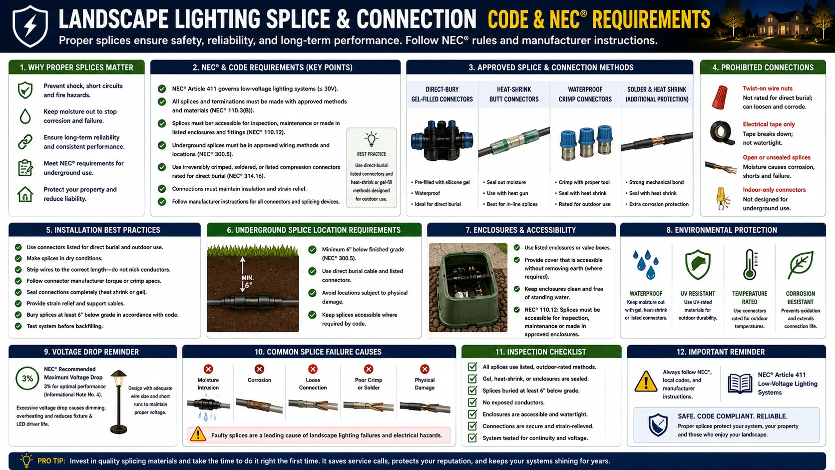
The Two NEC Rules That Work Together: 300.5(E) and 110.14(B)
The NEC's treatment of underground splices in landscape lighting is a two-part framework. One rule liberates the installer from a requirement many assume applies (junction boxes). The other imposes a requirement most installers don't know exists (listed connectors). Understanding both — separately and in combination — is the foundation of compliant landscape lighting connection practice.
"Direct-buried conductors or cables shall be permitted to be spliced or tapped without the use of splice boxes. The splices or taps shall be made in accordance with 110.14(B)."
What it means in practice:Landscape lighting wire runs can be spliced mid-run, at fixture connection points, and at wire extension joints without installing junction boxes at every connection point. This is what allows the standard landscape lighting installation approach — tap connections at each fixture location, wire extensions to add fixtures — without boxes buried at every tap. Low-voltage landscape circuits (≤30V per NEC 411) are specifically covered by this provision.
What it does NOT mean:This provision does not remove any connector quality or listing requirements. Its last sentence immediately cross-references 110.14(B) — the listing requirement — making clear that the two rules must be read together.
"Wire connectors or splicing means installed on conductors for direct burial shall be listed for such use."
What it means in practice:Any connector, wire nut, IDC clip, butt splice, or other device used to join conductors that will be buried in soil must carry a specific UL listing for direct burial. This listing is not the general UL mark that appears on standard wire nuts (UL 486A or 486B for indoor use). It is UL 486D — the sealed wire connector standard for wet/submersible/direct-burial applications. A product must specifically state "UL 486D Listed" or "Listed for Direct Burial" on its packaging. The standard UL mark without the 486D suffix does not satisfy 110.14(B) for underground applications.
Who it applies to:Every installer, professional or DIY, on every buried splice in every landscape lighting installation. No exemption for low voltage. No exemption for homeowner-installed systems. NEC 411 (which governs landscape lighting) does not modify or waive 110.14(B).
NEC 411.3: Low-voltage landscape lighting systems shall be listed (or composed of listed components). Since the system must be listed, NEC 110.3(B) applies.
NEC 110.3(B): Listed equipment shall be installed per its installation instructions. Listed landscape lighting transformers and systems specify compliant connection methods in their instructions — which reference NEC 110.14(B).
NEC 110.14(B): Underground splices require connectors listed for direct burial.
NEC 300.5(E): No junction box required, but splices must comply with 110.14(B).
The result: No box, but listed connector. Always. The two rules are not in conflict — they describe two different aspects of the same underground splice requirement.
UL 486D: What the Listing Requires and How to Verify a Specific Product
UL 486D is the specific listing standard that makes a wire connector suitable for direct burial use. Understanding what the standard actually tests — and how to confirm a product carries the listing before purchasing — is the practical implementation of the NEC 110.14(B) requirement.
What UL 486D Tests
UL Standard 486D ("Sealed Wire Connector Systems") tests wire connectors for performance in wet, damp, and direct-burial environments. The testing protocol goes significantly beyond standard wire connector tests (UL 486A/486B for dry indoor use). Key UL 486D test requirements include:
- Water immersion test: The assembled connector with wires must maintain electrical continuity and insulation resistance after submersion. This verifies the gel, silicone, or sealant compound fully encapsulates the splice.
- Freeze-thaw cycling: The connector must maintain its seal and electrical performance through repeated temperature cycling from below freezing to above freezing — simulating seasonal ground temperature changes.
- Soil burial performance: The connector material must resist degradation from soil contact, soil moisture, and soil chemistry (including acidic soils typical in mulched landscape areas).
- Mechanical strength: The splice must maintain conductor retention force after environmental exposure — preventing wire pullout from loose connections caused by soil movement.
- Dielectric integrity: The insulation system must maintain electrical isolation between conductors even when wet — preventing the leakage currents that cause GFCI trips.
How to Verify UL 486D Listing on a Specific Product
The verification steps, in order of reliability:
- Product packaging statement: Look for explicit text reading "UL 486D Listed," "Listed for Direct Burial," or "Suitable for Wet/Submersible/Underground Locations." The generic UL mark (the circle-UL symbol) without a specific standard number does not confirm 486D compliance.
- UL Product iQ database: Search the product name or UL file number at iq.ul.com. Products listed under UL 486D will show that standard in their listing details. This is the most authoritative verification method.
- Product data sheet: Professional landscape lighting suppliers (VOLT, Kichler, WAC) provide downloadable data sheets for connectors they stock. The data sheet will list the applicable UL standards. If UL 486D appears, the product is compliant.
- Manufacturer confirmation: For products where packaging is unclear, contact the manufacturer directly with the specific question: "Is this product listed under UL 486D for direct burial use?"
Products That Are UL 486D Listed (Commonly Available)
| Product | Type | UL Listing | Wire Range | Best Use |
|---|---|---|---|---|
| King Innovation DryConn (Blue/Black) | Gel-filled twist-on connector | UL 486D Listed | 10–16 AWG | Fixture tap connections, mid-run splices |
| King Innovation DryConn (Gray/Yellow) | Gel-filled twist-on connector | UL 486D Listed | 16–22 AWG | Fixture lead-to-wire connections, small gauge |
| 3M DBR/Y-6 Direct Bury Splice Kit | Wire nut + gel-filled tube | UL 486D, File E102356 | 14–10 AWG | Mid-span fixture connections |
| 3M UF Splice Kit (Standard) | Mechanical connector + heat-shrink | UL 486D Listed, submersible | 14–8 AWG (UF cable) | UF cable repairs, wire extensions |
| EPCO UF Splice Kit | Mechanical connector + heat-shrink | UL 486D, NEC 110.14(B) 300.5(E) | 14–8 AWG (UF cable) | UF cable repairs, wire extensions |
| Standard twist-on wire nut (any brand) | Twist-on connector, dry-location | UL 486A/486B only — NOT 486D | Varies | Indoor dry locations ONLY — code violation underground |
| Pierce-point / IDC landscape clip | Insulation-displacement connector | Not UL 486D listed | 16–18 AWG | Above-grade fixture connections only — not for burial |
A splice can be properly made and still be part of a weak installation if the transformer is overloaded, the wire is damaged, the connector is not documented, or the fixture run has excessive voltage drop. Once each splice is checked for wet-location or direct-burial suitability, use the NEC low-voltage lighting field inspection checklist to confirm the larger system: listed transformer, safe primary power, correct cable routing, fixture ratings, connector condition, grounding or bonding requirements where applicable, and final documentation photos before the repair is considered complete.
A properly sealed splice protects more than the electrical connection—it also helps preserve the cable insulation surrounding the conductors. Our Landscape Lighting Insulation Breakdown Guide explains how insulation damage contributes to moisture intrusion, corrosion, and long-term reliability issues.
Why Standard Wire Nuts Are a Code Violation in Underground Landscape Lighting
Standard wire nuts are the most common non-compliant connector in landscape lighting installations — partly because they are ubiquitous, cheap, and familiar, and partly because a reasonable homeowner assumption is that "waterproof tape" or "silicone dip" converts them to an adequate underground connector. Neither assumption is correct, and both fail both legally and physically.
The Legal Problem: Listing Cannot Be Field-Modified
NEC 110.14(B) requires the connector to be "listed for such use." A listing is a product certification from an NRTL (Nationally Recognized Testing Laboratory) like UL or ETL. It is not a material property of the connector itself — it is a certification that the complete connector product, as manufactured, has been tested and found to meet the applicable performance standard. Wrapping a standard wire nut in electrical tape does not change the connector's UL 486A/B listing to a UL 486D listing. Dipping it in silicone does not change its listing. The listing reflects testing of the product as manufactured. Field modification of an unlisted product for an application it was not listed for does not satisfy the NEC listing requirement under any interpretation of 110.3(B) or 110.14(B).
The Physical Problem: Why Tape and Sealant Fail Underground
Even setting aside the legal issue, the physical performance of tape-wrapped or sealant-dipped standard wire nuts in direct burial applications is poor over time:
- Electrical tape: PVC electrical tape loses adhesion in constant soil moisture conditions. Below-grade temperature cycling causes the tape to shrink and crack. After 2–3 freeze-thaw cycles in moist soil, taped wire nut connections routinely develop moisture intrusion. Tape is not a sealed encapsulant — it is a wrapped barrier that moisture can eventually wick under.
- Scotch-type coating or silicone dip: While better than tape, applying a non-listed sealant to the exterior of a connector does not prevent moisture wicking along the conductor insulation jacket and into the connector through the wire entry point. UL 486D-listed gel-filled connectors work by internal encapsulation — the gel fills the void around the splice from the inside, displacing air and blocking the capillary pathway that runs along the conductor. External coatings do not replicate this.
- Soil chemistry: Soil acids (particularly in mulched beds where landscapers apply bark mulch or wood chips) attack copper conductors at unprotected splice points, creating oxide layers that raise resistance. High-resistance splices generate heat under load — a fire risk in organic mulch.
The most common objection to the listing requirement is the observation that many landscape lighting systems with standard wire nuts or pierce-point connectors "work fine" for years. This objection misunderstands how connection failure progresses. Non-listed buried connectors don't typically fail immediately — they fail gradually. A corroding splice increases resistance over months and years. As resistance rises, voltage drop at fixtures beyond the splice increases (explaining the gradual dimming that many homeowners attribute to lamp aging). Eventually the splice fails completely (explaining the "zone went out" call). Throughout this process, the splice may also be generating heat as it transitions from a low-resistance to a high-resistance connection — a process invisible at the surface. The failure is not always visible before it occurs.
Pierce-Point Connector Failure: Why the Connector in Your Lighting Kit Isn't Enough
Every consumer landscape lighting kit sold at big-box retailers includes some form of quick-connect fixture connector — typically a pierce-point or insulation-displacement connector (IDC) that clamps onto the main wire without stripping it. These connectors are the most widely installed and the most widely failing connection method in residential landscape lighting.
How Pierce-Point Connectors Work and Where They Fail
A pierce-point connector (sold under various product names — quick clip, snap connector, saddle connector) works by driving one or more metal pins through the insulation jacket of the main landscape wire, making contact with the copper conductor inside. The fixture lead wires connect to the other side of the connector. No wire stripping is required. Installation is fast — squeeze the connector onto the wire, close it, done.
The design works acceptably above grade in a dry location where the connection is accessible for inspection and replacement. It fails progressively in buried, soil-contact applications for four specific reasons:
The Code Problem with Pierce-Point Connectors in Buried Applications
Pierce-point IDC connectors are not listed under UL 486D for direct burial. They carry UL listings for above-grade, dry-location connector use — consistent with their design intent as accessible, field-adjustable connectors. Using them in a buried application does not satisfy NEC 110.14(B)'s requirement for direct-burial-listed connectors. The practical failure pattern described above explains exactly why UL 486D testing is necessary — it would reveal these failure modes before the product is certified, ensuring that only products that survive underground conditions reach that listing level.
The Correct Use of Pierce-Point Connectors in Landscape Lighting
Pierce-point connectors have a legitimate above-grade role: connecting fixture leads to main cable wire at fixture locations that are accessible (not buried), where the connector sits in the fixture housing or above ground level. In this application — accessible, above-grade, not in soil contact — they can be inspected, replaced, and are not subject to the continuous soil-moisture exposure that causes buried failures. The practical guidance: use pierce-point connectors for above-ground fixture connections only, and use UL 486D-listed gel-filled connectors for any connection point that will be covered in soil or mulch.
When I dig up a landscape lighting splice to diagnose a failed zone, I can almost always tell from a foot away what I'm going to find. Green-gray wire jacket coloration along the last 2–3 feet before the connection point means moisture wicking. When I open the connector — if it's a pierce-point type — the pin contact area looks like a small circle of green-black corrosion on the copper conductor, with the wire jacket wet or slightly decomposed where the pin penetrated. A properly installed DryConn-type gel-filled connector, by contrast, comes out with the splice fully encased in silicone gel, the copper conductors still bright, and the connection electrically perfect. The visual difference is dramatic. The functional difference is the whole system.
Moisture intrusion remains one of the most common causes of outdoor electrical failures. Once water reaches exposed conductors, corrosion can slowly develop even when the system appears to function normally. Seasonal lighting systems experience similar issues during storage, which is why our Christmas light corrosion prevention guide covers practical methods for keeping electrical contacts dry, protected, and operational from one season to the next.
The Four NEC-Compliant Splice Methods for Landscape Lighting
NEC 110.14(B) compliant landscape lighting splices fall into four categories, each with different performance characteristics, appropriate applications, and installation requirements. Understanding which method is best for which application is the practical implementation of code compliance.
FILL
Pre-filled with silicone or dielectric gel inside the connector body. Strip both wires, insert together, twist clockwise until the wires resist further turning — excess gel squeezing out confirms complete encapsulation. The gel displaces all air from the splice area, preventing oxidation and blocking moisture capillary pathways. UL 486D Listed. Products: King Innovation DryConn (multiple sizes), 3M DBR/Y-6. Wire range: 10–22 AWG depending on connector size. Use for: fixture lead-to-main-cable connections, mid-run tap connections at fixture locations, wire-to-wire landscape circuit splices.
SHRINK
Combines a mechanical connector (which provides the electrical joint) with adhesive-lined heat-shrink tubing that, when heated, shrinks to form a continuous waterproof seal over both the connector and the adjacent cable jacket — replicating the factory cable jacket across the entire splice zone. UL 486D Listed (submersible). Products: 3M UF Splice Kit (Standard or Stretcher), EPCO UF Splice Kit. Wire range: 8–14 AWG UF-type cable. Use for: main cable repairs, wire run extensions, any splice where the highest long-term seal integrity is needed, any splice subject to soil movement or groundwater exposure. Requires a heat source (heat gun preferred, propane torch acceptable with care). More labor-intensive than gel-filled but provides superior long-term performance.
KIT
Mechanical compression connector plus separate gel or sealant encapsulation (either a prefilled tube, a clamshell enclosure filled with gel, or a wraparound sealant assembly). Unlike heat-shrink kits, these do not require a heat source. Products include various manufacturer-specific inline splice kits designed for irrigation and landscape wire. UL 486D listing must be verified per kit — not all inline mechanical kits carry 486D. Wire range and application specifics vary by product. Appropriate when heat-shrink tooling is unavailable and a gel-filled connector is too small for the splice configuration.
+ INS
NEC 110.14(B) explicitly permits splices made by "brazing, welding, or soldering with a fusible metal or alloy" — provided the splice is first made mechanically and electrically secure without solder, then soldered, then covered with insulation equivalent to the conductor rating. For direct burial, this requires the completed soldered splice to be covered with a listed insulation device or equivalent insulation — typically an adhesive-lined heat-shrink tube rated for underground use. This method is technically compliant but is the most labor-intensive option and requires more specialized skill. It is not commonly used in landscape lighting field installations. If soldering is used, note that the solder must not be the primary mechanical connection — conductors must first be mechanically twisted or joined, then soldered to lock them.
A poor splice and a high-THD driver can produce similar symptoms, including flicker, buzzing, unstable controls, and voltage changes under load. The difference is visible in the measurements: a failed splice causes a localized voltage drop, while harmonic distortion changes the shape of the current waveform and may affect multiple fixtures or circuits at once. The LED driver THD field diagnostic guide explains how to measure current harmonics and avoid replacing connectors when the real problem is driver-to-source compatibility.
Step-by-Step Installation for the Two Primary Methods
The gel-filled connector and heat-shrink splice kit are the two most practical and most commonly used compliant methods for landscape lighting. Complete procedures for both.
Method 1: Gel-Filled Waterproof Connector (DryConn Type)
Method 2: Heat-Shrink Direct-Burial Splice Kit (3M UF Splice Kit Type)
Mapping Connector Types to Installation Contexts
Not every connection in a landscape lighting system has the same risk profile or requires the same connector type. This table matches specific installation contexts to the appropriate connector method, with the code basis for each recommendation.
| Connection Context | Burial Status | Required Connector Type | Code Basis | Best Practical Choice |
|---|---|---|---|---|
| Fixture lead to main cable — buried under mulch or soil | Buried / soil contact | UL 486D listed only | NEC 110.14(B) | Gel-filled waterproof connector (DryConn or equivalent) |
| Fixture lead to main cable — above grade, in fixture housing | Above grade, accessible | Listed for use (general) | NEC 110.14(B) general | Pierce-point IDC connector is acceptable here — accessible and not buried. DryConn also acceptable. |
| Main cable splice / repair / extension — buried | Buried / soil contact | UL 486D listed only | NEC 110.14(B), 300.5(E) | Heat-shrink direct-burial splice kit (3M UF Splice Kit or EPCO equivalent) |
| Main cable splice — in above-grade junction box | Above grade, enclosed | Listed for wet location if box may accumulate moisture | NEC 300.5(B) — underground enclosures are wet locations | Gel-filled connector — provides moisture protection even in an above-grade box exposed to rain intrusion |
| Connection at transformer terminal block | Above grade, transformer cabinet | Terminal connection per 110.14(A) | NEC 110.14(A) — terminal connection | Insert stripped wire into terminal, tighten set screw. No wire connector needed. See transformer guide. |
| Wire splice inside an underground junction box or valve box | Below grade enclosure — wet location | Listed for wet location minimum; UL 486D preferred | NEC 300.5(B) — underground interiors are wet locations by definition | Gel-filled waterproof connector. Even in a "sealed" underground box, moisture intrusion is common. UL 486D is the conservative correct choice. |
The Underground Junction Box: Wet Location by Definition
A point that surprises many installers: NEC 300.5(B) states that "the interior of enclosures or raceways installed underground shall be considered to be a wet location." This means that a splice made inside an underground junction box — even a sealed one — is legally in a wet location and requires connectors appropriate for wet locations. UL 486D-listed gel-filled connectors satisfy this requirement. This is why the IAEI and NEC commentary both advise that underground box splices use the same listed-for-burial connectors as boxless direct-burial splices.
Practical system design to minimize buried splices: Every buried splice is a future vulnerability point regardless of connector quality. Professional landscape lighting system design minimizes buried mid-run splices through two practices: (1) Hub wiring — running the main cable to a central hub location and making all fixture connections at the hub rather than at distributed mid-run points. This concentrates all connections at one inspectable, replaceable location. (2) Pre-planning run lengths — laying out fixture positions before trenching so main cable runs terminate at, or very near, fixture positions rather than requiring extensions. See the wiring guide and layout guide for hub wiring layout techniques.
Splice & Connection Code Requirements FAQ
My landscape lighting has been running for 8 years with standard wire nuts and tape. Do I need to replace them?
Legally, yes — they are non-compliant with NEC 110.14(B) and have been since installation. Practically, the answer depends on system performance. If your system is showing any symptoms of increasing voltage drop (gradually dimming fixtures over time, zones that were bright when new but are now noticeably dimmer, or sections of the system that have gone completely dark), the buried standard wire nut connections are the most likely cause. Diagnosing this is straightforward with a multimeter: measure voltage at the first fixture on the run and at the last fixture. If there is more than 1V difference attributable to connections rather than wire length (compare to the voltage drop calculation for your run — see the voltage drop calculator), a corroded splice is the likely culprit. Upgrading to UL 486D listed connectors when you have access (during re-landscaping, irrigation work, or system expansion) is the right approach. Digging up functioning systems solely to replace connectors is generally not warranted unless symptoms appear.
Does the UL 486D listing requirement apply to low-voltage (12V) landscape lighting circuits, or only to line voltage?
It applies to low-voltage landscape lighting circuits. NEC 110.14(B) states that "wire connectors or splicing means installed on conductors for direct burial shall be listed for such use" — there is no voltage exemption or low-voltage exclusion in this provision. NEC Article 411 (which governs low-voltage landscape lighting) does not modify 110.14(B)'s requirements. Additionally, since NEC 411.3 requires the landscape lighting system to be listed, NEC 110.3(B) mandates installation per the listing's instructions — which for UL 1838-listed transformers and systems reference compliant connection methods consistent with 110.14(B). The low-voltage exemptions in the NEC (primarily burial depth reductions under Table 300.5) do not extend to connector listing requirements.
Can I use a standard wire nut inside a waterproof landscape lighting junction box that is buried?
Technically no, for two reasons. First, NEC 300.5(B) classifies underground enclosure interiors as wet locations by definition — meaning any connection inside a buried junction box is in a wet location and requires wet-location-listed connectors. Second, NEC 110.14(B)'s requirement for direct-burial-listed connectors for "conductors for direct burial" applies to conductors installed in below-grade conditions. The interior of a buried box is a below-grade, wet-location environment. The practically correct choice for any connection in a buried box is a UL 486D-listed gel-filled connector — this satisfies both the wet location requirement and any direct-burial connector requirement simultaneously. If you are using a buried junction box to make connections (rather than using a boxless direct-burial splice), see the junction box requirements guide for additional requirements.
My new landscape light fixture came with a quick-connect clip. Can I use it if I bury it?
No — quick-connect clips (pierce-point IDC connectors) included with consumer landscape lighting fixtures are not listed under UL 486D for direct burial. They are designed for above-grade fixture connections in accessible locations. When buried, they fail through the progressive corrosion mechanism described in detail above: moisture wicking, copper oxide formation, increasing resistance, and eventual connection failure — often within 2–5 years in wet soil conditions. The compliant approach: use the included quick-connect only if the connection point will remain above grade (in the fixture housing, above the mulch line). For connections that will be at or below grade, strip both wires and connect with a UL 486D gel-filled connector (DryConn or equivalent). This takes 90 additional seconds per fixture and is the difference between a splice that may last 5 years and one that will last 20+.
How do I find buried splice locations in an existing landscape lighting system to diagnose or replace connectors?
Buried splice locations in existing systems can be located through several methods. The best approach: consult any installation documentation (photographs taken before backfilling, notes in a landscape plan). If documentation doesn't exist, splice locations are most commonly at fixture connection points — within 12–18 inches of each fixture stake along the wire run, at the depth the main cable was buried. A tone generator / wire tracer (available at rental centers and electrical supply houses) can locate buried wire runs, and experienced users can detect changes in signal strength or reflection that indicate connector locations. For systems showing voltage drop symptoms, systematic voltage measurement at each fixture moving progressively from the transformer identifies which segment contains the high-resistance connection — see the voltage drop guide and one zone not working guide for the diagnostic procedure.
Related Electrical Code and Wiring Guides
- Electrical Code Safety Guide
- Wire Burial Depth Code
- Junction Box Requirements
- Load Calculation & Code Compliance
- Voltage Drop Code & NEC Requirements
- GFCI Requirements NEC 2026
- Arc Fault & GFCI Code Requirements
- NEC 2026 Updates
- Permit Requirements
- Grounding and Bonding Guide
- Transformer Mounting Code
- Contractor Licensing Requirements
- Insurance & Liability Guide
- Connectors Guide
- How to Wire Landscape Lighting
- Wire Gauge Guide
- Voltage Drop Guide
- Voltage Drop Calculator
- One Zone Not Working
- Landscape Lighting Maintenance
- Transformer Sizing Guide
- Landscape Lighting Layout Guide