
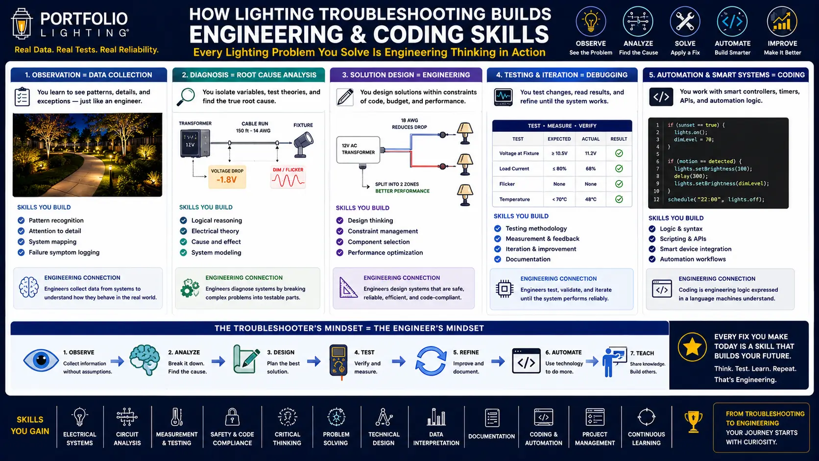
The Shared Logical Framework: Why These Two Things Are the Same Problem
Before mapping the specific parallels, it is worth stating precisely what I mean when I say electrical troubleshooting and software debugging use the same logical framework. I am not saying they feel similar, or that they both require patience, or that they both involve computers in some distant sense. I am saying the sequence of cognitive operations is identical.
Both processes begin with a symptom — an observable deviation from expected behavior. The system was working; now it is not. Or it is working, but not correctly. The symptom is not the problem. The symptom is the evidence that a problem exists somewhere in the system. A landscape lighting zone that does not illuminate is a symptom. A program that does not produce expected output is a symptom. In neither case is the right first response to start randomly replacing parts or rewriting code. The right first response is to ask: where in the system did the deviation from expected behavior originate?
Both processes then use a sequence of binary tests to narrow the search space. A binary test is any observation that divides the possible problem space into two subsets — those explanations that are still possible given the test result, and those that are now eliminated. In electrical troubleshooting, measuring voltage at the transformer output terminals is a binary test: either voltage is present (which eliminates the transformer as the cause of no downstream power) or it is not (which localizes the problem to the transformer or its power supply). In software debugging, inserting a print statement or breakpoint at a specific line is a binary test: either the variable has the expected value at that point (which eliminates all prior code as the source of the bug) or it does not (which localizes the bug to the code executed before that point).
Both processes terminate at root cause — the specific condition that, if corrected, resolves the symptom. A corroded wire splice that interrupts circuit continuity is a root cause. A null pointer dereference that causes a runtime exception is a root cause. Both look very different on the surface. Both are reached through the same sequence of narrowing tests applied to a system model.
The logical framework shared by electrical troubleshooting and software debugging has a formal name in computer science: it is a binary search applied to a causal model. You systematically halve the search space with each test, using the system's structure as your map. Whether the system is a circuit or a program, the algorithm is the same.
Why This Matters for STEM Education
The educational implication is concrete. A student who has genuinely debugged a landscape lighting system — traced power from the transformer through each zone, measured voltage at each fixture, isolated a failed photocell or corroded connector through systematic testing — has practiced the exact cognitive operations that software debugging requires. They have done it with physical feedback: the multimeter reading changed, the light came on, the problem was visibly solved. That physical concreteness reinforces the logical framework in a way that abstract code on a screen often cannot for beginning programmers.
This is not a metaphor. It is a transfer of domain-independent reasoning skills through a domain that provides immediate, tangible feedback.
Side-by-Side Diagnostic Flowcharts: Electrical vs Software
These two flowcharts document real diagnostic workflows — one from landscape lighting troubleshooting practice, one from software debugging methodology. Both follow the same branching elimination structure. The structural identity becomes immediately visible when you read them in parallel.
❓ Voltage present? Expected: 11.5–12.5V
❓ Syntax valid? No parser or compiler errors?
❓ Continuity present throughout run?
❓ Input data / initial state correct?
❓ Error in your code or a dependency?
Full Diagnostic Vocabulary Comparison: Electrical vs Software
Every concept in electrical troubleshooting has a direct structural equivalent in software debugging. This table maps the complete shared vocabulary — not loosely, but precisely. Each pair describes the same diagnostic operation or system condition in a different medium.
| Diagnostic Concept | ⚡ In Electrical Systems | 💻 In Software Systems |
|---|---|---|
| State inspection | Measuring voltage at a node with a multimeter — determines whether power is present and at what level at a specific point in the circuit | Inspecting a variable value with a debugger or print statement — determines whether program state is correct at a specific point in execution |
| Continuity check | Testing wire continuity with a multimeter in continuity mode — confirms an unbroken electrical path exists between two points | Code path tracing — confirming a specific execution path is actually reachable from the program entry point under the conditions being tested |
| Open circuit | A complete break in the electrical path — no current flows, downstream components receive no power. Caused by a broken wire, corroded splice, or failed connector | A missing or unreachable function call — code that should execute never runs because a condition is never met, a function is never called, or a module is never imported |
| Short circuit | An unintended low-resistance path that allows excessive current to flow, tripping protection devices. Caused by wire insulation failure or contact between conductors | An infinite loop — code that executes repeatedly without a valid exit condition, consuming processor resources until the program crashes or becomes unresponsive |
| Voltage drop | Reduction in available voltage at downstream fixtures caused by wire resistance over distance. Progressive — each additional foot increases the drop at the most distant fixture | Data pipeline degradation — a value that starts correct at input is corrupted or reduced by successive processing steps, producing wrong output at the end of the chain |
| Transformer overload | A transformer carrying more wattage than its rated capacity — producing reduced output voltage, overheating, and potential shutdown | Memory overload / stack overflow — a program attempting to use more memory than available, or a recursive function that exceeds the call stack depth |
| Ground fault | An unintended path for current to flow to ground — often through water-damaged insulation. Causes GFCI trips and potential safety hazard | A null pointer dereference — a program attempting to access a memory location that has not been allocated or has been freed. Causes runtime crash |
| Intermittent failure | A fault that appears and disappears — typically a loose connection, a connector with marginal contact, or a photocell near its light threshold. Hardest electrical fault to diagnose | A race condition — a bug that occurs only when two processes execute in a specific timing relationship. Hardest software fault to reproduce and diagnose |
| Cascading failure | One failed component causing progressive failure of downstream components — a failed transformer produces low voltage that causes driver overheating that causes LED failure | Exception propagation — an unhandled error in one function causes calling functions to fail in sequence, producing an error message that describes the last failure rather than the root cause |
| Photocell calibration | A photocell set to the wrong sensitivity threshold — activates too early or fails to activate at dusk. A timing boundary condition failure | An off-by-one error — a loop using < instead of <= executes one iteration too many or too few. A boundary condition failure with an identical diagnostic signature |
| Load balancing | Distributing fixture load evenly across multiple transformer zones to prevent any zone from exceeding wire voltage drop limits or transformer capacity | Distributing request handling evenly across multiple server instances to prevent any instance from exceeding memory or CPU capacity |
| Zone isolation | Disconnecting one zone at a time to determine which zone contains a fault — a divide-and-conquer approach to narrowing the fault location | Binary search debugging — commenting out or disabling half the codebase at a time to determine which half contains a bug, then recursively narrowing |
| Tap adjustment | Changing the transformer output tap to compensate for voltage drop on long runs — treating a symptom without addressing the underlying wire gauge cause | Hardcoding a workaround value instead of fixing the underlying algorithm — produces the right answer for known test cases but will fail on edge cases |
| IP rating failure | A fixture whose IP seal has degraded, admitting moisture that slowly corrodes driver components — a failure that develops silently over months before becoming visible | A memory leak — a program that gradually consumes increasing memory, performing normally until available memory is exhausted hours or days after the session began |
Scroll horizontally on mobile to see all three columns.
Multimeter to Code: How Each Physical Measurement Maps to a Programming Operation
A digital multimeter is a state inspection tool — it reads the condition of a circuit at a specific point in time at a specific location. This is precisely what a debugger does for a program. The specific measurement modes of a multimeter map to specific debugging operations with remarkable precision.
🔌 Voltage (DC/AC)
⏺ Continuity Mode
🔳 Resistance (Ohms)
📈 Current (Amps)
🕑 Frequency
🌡️ Temperature (Thermocouple)
I've had homeowners dig through my parts pages for hours — sometimes coming back three or four times over a couple of weeks looking for a transformer, a photocell, a replacement module. And more often than I can count, when they finally described the actual symptom to me, the answer was a $15 multimeter and twenty minutes of their time. One reading at the transformer terminals, one at the fixture, and the problem was right there in the numbers. That kept happening often enough that I started to see something bigger in it: most lighting problems — and honestly most technical problems in general — aren't as complicated as they feel when you're standing in a dark yard wondering what went wrong. The complexity usually comes from not knowing where to look, not from the problem itself. A systematic approach almost always finds a simple answer. That's as true for a failed splice in a low-voltage run as it is for a bug buried three functions deep in someone's code.
5 Real Landscape Lighting Failures — With Their Exact Software Parallels
These are not hypothetical scenarios. These are failure patterns I have diagnosed in real residential landscape lighting systems over 25 years of field work. Each is paired with its structurally identical software failure — the same logical pattern, the same diagnostic approach, different domain.
Transformer Hum with Full Output — Transformer Internal Resonance
Electrical scenario: A homeowner calls about a buzzing hum from the transformer housing. All landscape lights are working normally. Voltage output is 12.2V — within spec. The hum is intermittent, louder in the evening when the load is fully energized.
Field diagnosis: The hum is produced by magnetostrictive vibration in the toroidal transformer core — the laminated iron core physically vibrates at the 60Hz supply frequency. This is normal physics. The hum has become audible because the mounting screws have loosened over years of thermal expansion cycles, allowing the housing to amplify the vibration. The system is functioning correctly; the resonance is a mechanical issue with the mounting, not an electrical failure. Diagnosis: vibration resonance from loose mechanical mounting, not electrical fault. Fix: retighten mounting hardware, apply vibration-dampening pad under transformer housing.
⚡ Electrical diagnostic logic
Symptom (audible hum) is not correlated with functional failure (full output, correct voltage). The symptom is in a different system layer than the electrical circuit — it is mechanical. Separating symptom layer from failure layer reveals the actual root cause is not in the electrical domain at all.
💻 Software parallel
A program that logs excessive warning messages while producing correct output. The warnings are real but not correlated with the functional output. A developer who treats the warnings as the primary failure will never find the root cause. The actual issue may be a deprecated API call or a configuration mismatch — a different system layer than the computation producing correct results.
Lights Work During Day, Not at Night — Photocell Miscalibration
Electrical scenario: Landscape lights that should activate at dusk are not turning on. Manual override confirms the transformer and fixtures are functional — everything illuminates on manual mode. The photocell is the suspect. Testing the photocell sensitivity: it is set to activate at a very low light level — roughly twilight rather than dusk. In practice, this means the system waits until it is fully dark to activate, appearing broken to a homeowner who expects lights at dusk. The photocell is not failed — it is miscalibrated.
Field diagnosis: The photocell sensitivity threshold is set incorrectly. The sensor is working exactly as calibrated — it just requires lower ambient light than the user expects. Root cause: configuration error, not component failure. Fix: adjust sensitivity dial on photocell to activate at higher ambient light level.
⚡ Electrical diagnostic logic
Distinguish between component failure and component misconfiguration. The photocell is not broken — it is working correctly to a wrong specification. This class of fault requires testing the component to its documented specification before concluding it has failed. Many unnecessary component replacements happen because a misconfigured working component is diagnosed as a failed component.
💻 Software parallel
A program whose condition threshold is set incorrectly. An if-statement that checks if (temperature > 100) when the intended logic is if (temperature > 80) — the code is syntactically valid, semantically correct for its stated condition, but functionally wrong because the threshold was specified incorrectly. Debugging reveals no code error; the specification was wrong.
Flickering LEDs Exclusively After Rain — Corroded Wire Splice
Electrical scenario: One zone of path lights flickers intermittently. The flickering is completely reliable in one condition: it always occurs within 2–4 hours after rain and resolves after several dry days. This is the most valuable diagnostic clue — a failure correlated precisely with an environmental condition almost always has its root cause at a moisture exposure point. Field investigation focuses on all splice connections in the affected zone. One inline connector splice shows green copper oxide corrosion on the wire contact surfaces inside the connector housing — moisture has been entering through a partially inserted connector cap, depositing minerals on the copper, creating intermittent high resistance at the junction.
⚡ Electrical diagnostic logic
Environmental correlation is diagnostic gold. A failure that occurs only under specific conditions is not random — it is caused by whatever that condition introduces. Rain introduces moisture; moisture lowers the insulation resistance of corroded connections; intermittent low resistance creates flickering. The diagnostic path is: identify the environmental condition → identify what that condition changes in the circuit → locate where that change has the most impact.
💻 Software parallel
A race condition that manifests only under high server load. The bug exists at all times but only produces incorrect behavior when two processes execute within a specific timing window — a window that only opens when the system is under enough concurrent load to slow specific operations. Reproducing the failure requires creating the environmental condition (high load) that exposes the underlying timing vulnerability.
Last Three Fixtures on Run Progressively Dim — Voltage Drop Cascade
Electrical scenario: Eight path lights on a single zone run. The first five near the transformer are bright and correctly color-balanced at 2700K warm white. The last three are noticeably dimmer and slightly bluer in color temperature. Voltage measurement at the first fixture: 11.9V. Voltage at the last fixture: 10.2V. A 1.7V drop across the run — the wire gauge (16AWG kit wire) is too small for the run length (140 feet) at this load (8 × 4W = 32W). The brightness gradient exactly matches the voltage gradient along the wire. Root cause: undersized wire gauge producing progressive voltage drop across the run length.
⚡ Electrical diagnostic logic
The gradient pattern — bright near the source, dim at distance — is the diagnostic signature of a progressive resistance fault. A failed component produces a binary failure (light or dark); a resistance fault produces a gradient. The gradient points directly to wire resistance as the cause, and measurement at multiple points along the run quantifies it precisely.
💻 Software parallel
A data processing pipeline where the output becomes progressively less accurate with each transformation stage. An image compression algorithm that applies lossy compression at each step — the first processed frame looks nearly perfect; the tenth looks noticeably degraded; the fiftieth is barely recognizable. Each stage introduces small error; the errors accumulate. The gradient of degradation identifies the pipeline as the source, not any single processing step.
Transformer Trips Breaker Randomly — Intermittent Ground Fault
Electrical scenario: A 150W landscape transformer trips its internal breaker 2–3 times per week at random times. Resetting the breaker restores normal operation. The system appears to work normally between trips. No single zone consistently causes the trip — it occurs with all zones connected. Water ingress inspection finds a section of direct-burial wire running through a low area that floods briefly after heavy rain. When the flooded soil contacts the wire, the water provides an unintended current path from the wire to ground — a ground fault that increases total current draw above the transformer's protection threshold, tripping the breaker. After rain drains, the fault path disappears and the transformer resets normally.
⚡ Electrical diagnostic logic
A fault that produces no consistent symptom pattern except timing correlation with specific environmental events. The key insight is that random-appearing electrical failures are rarely truly random — they have an environmental trigger that has not been identified yet. Logging the exact time of each trip against weather data revealed the rain correlation within two weeks of monitoring.
💻 Software parallel
A server crash that occurs at apparently random times with no consistent error message. Logging reveals the crashes correlate with a specific third-party API call that fails when that provider's servers are under load — an event that occurs unpredictably from the local server's perspective. The crash appears random; the cause is deterministic but depends on an external system's state.
Voltage Drop as a Software Pipeline Problem: A Deep Technical Parallel
Of all the parallels between electrical diagnostics and software systems, voltage drop in a landscape lighting circuit is the one that maps most precisely to a class of software problem that computer science students struggle with: cumulative error in data processing pipelines. The math, the diagnostic approach, and the remediation strategy are structurally identical.
The Electrical Mechanics of Voltage Drop
In a 12V low-voltage landscape lighting circuit, wire resistance causes a voltage reduction proportional to both the current flowing through the wire and the length of the wire. Ohm's Law: V = I × R. For a 16AWG wire run of 100 feet carrying 4 amps (48 watts), the round-trip resistance of the wire is approximately 1.6 ohms, producing a voltage drop of 6.4V — leaving only 5.6V at the most distant fixture. The fixture goes completely dark at that voltage. The wire did not fail. The transformer did not fail. No component failed. The accumulated resistance of an undersized conductor over a long run consumed the voltage that was supposed to reach the load.
The progressive nature of the problem is the key teaching point. Each foot of wire adds a small amount of resistance. Each additional fixture adds more current draw. Neither alone is a catastrophic failure — they are small incremental degradations that compound. The last fixture on the run receives the fully accumulated voltage drop from the entire run length. See the Wire Gauge and Ampacity Database for the complete resistance and voltage drop data by gauge and run length.
The Software Equivalent: Data Precision Loss in Pipelines
A direct software parallel is floating-point precision loss in a multi-stage numerical computation pipeline. Each arithmetic operation on a floating-point number introduces a tiny rounding error — the least significant bits are rounded to fit the finite precision of the floating-point representation. One operation introduces negligible error. One hundred operations may introduce cumulative error that makes the final result meaningfully wrong.
A physics simulation that applies 10,000 time steps to model a trajectory starting with 1.0000000000 produces a final position that may be 1.0000047829 or 0.9999952171 instead of the mathematically exact 1.0000000000 — not because any single step was wrong, but because the accumulated rounding error from 10,000 steps compounded. The simulation did not fail. The algorithm was correctly implemented. The cumulative resistance of an undersized numerical representation over a long computation consumed the precision that was supposed to carry through to the final result.
The Identical Diagnostic Approach
In both cases, the diagnostic procedure is: measure the value at multiple intermediate points along the path, identify where the degradation begins, and the cause is located between the last correct measurement and the first degraded one. For voltage drop: measure voltage at the transformer, at the first fixture, at the midpoint of the run, and at the last fixture. For numerical precision loss: print the computed value after each pipeline stage. In both cases, the measurement technique is the same — systematic intermediate-point inspection — and the insight it yields is the same — locate the stage or segment where the degradation originates. This is invariant checking in software engineering and Kelvin probing in electrical engineering. Different names. Identical logic.
Step up wire gauge (10AWG instead of 16AWG) — lower resistance per foot means less voltage drop per unit length across the run
Split zones — run two shorter wire runs from the transformer instead of one long run, reducing the effective run length and therefore the accumulated resistance
Adjust transformer tap — increase source voltage from 12V to 14V to compensate for the resistance-caused drop, so the last fixture still receives 11.5V after the drop occurs (this treats the symptom without addressing the root cause)
Move fixtures closer to the transformer — reduce the physical distance the current must travel through resistance
Step up numerical precision (double instead of float, or arbitrary precision libraries) — lower relative rounding error per operation means less precision loss per step across the pipeline
Split pipeline into parallel branches — process subsets of data in separate, shorter pipelines and merge results, reducing the number of precision-degrading operations applied to any single value
Apply compensation at output — add a correction term to the final result based on known systematic bias (treats the symptom without addressing the accumulated error source)
Restructure algorithm to reduce operation count — use a mathematically equivalent formulation that requires fewer floating-point operations to reach the same result
A Real Diagnostic Workflow: From Breaker Trip to Root Cause
The most powerful illustration of how electrical troubleshooting mirrors algorithmic thinking is a complete field diagnostic sequence. Below is a real workflow — the kind a practitioner actually follows, step by step, with specific measurements and decision points at each stage. This is not a simplified diagram. This is the actual sequence.
The scenario: a 150W low-voltage transformer trips its internal breaker intermittently. The homeowner has already reset it twice. No obvious cause. Here is the exact diagnostic sequence.
Skills Built: Lighting Troubleshooting to Engineering and Coding Equivalents
Every hands-on skill developed through landscape lighting diagnostics has a direct equivalent in formal engineering and computer science. This table maps the practical to the academic — showing precisely which transferable competencies each troubleshooting activity develops.
| ⚡ Lighting Troubleshooting Skill | 💻 Engineering / CS Equivalent | 🎓 Academic Context |
|---|---|---|
| Voltage testing at multiple circuit nodes | Data validation and state inspection — verifying that a value is correct at each stage of a process before proceeding | Computer science: debugging, unit testing, assertion checking |
| Isolating fixture zone failures by disconnection | Root cause analysis — systematically eliminating non-causative factors to identify the specific source of a failure | Software engineering: binary search debugging, fault isolation |
| Wire continuity tracing along a run | Systems mapping — following data or signal flow through a connected system to identify where an expected path is interrupted | Electrical engineering: signal tracing; CS: call stack analysis |
| Testing transformer timer and photocell sequences | Logic sequencing — verifying that conditional triggers fire in the correct order under the correct input conditions | Computer science: control flow testing, conditional logic validation |
| Diagnosing voltage drop across long wire runs | Performance degradation analysis — measuring the cumulative effect of resistance or inefficiency across a processing pipeline | Systems engineering: impedance matching; CS: algorithmic complexity |
| Identifying intermittent failures after rain events | Environmental dependency testing — reproducing failures by recreating the specific conditions under which they occur | Software QA: regression testing, environment-specific bug reproduction |
| Calculating wire gauge for a given load and run length | Capacity planning — selecting system resources (bandwidth, memory, processing power) proportional to expected demand | Systems engineering: load calculation; CS: resource allocation |
| Setting up smart lighting automation schedules | Automation programming — defining event-driven logic that executes specific actions under specific conditions at specific times | Computer science: event-driven programming, scheduling algorithms |
| Reading IP rating specifications for fixture selection | Interface specification analysis — evaluating whether a component meets the environmental or operational requirements of the system it will join | Systems engineering: component specification; CS: API compatibility |
| Distributing fixture load across multiple transformer zones | Load balancing — distributing demand across multiple processing units to prevent any single unit from exceeding its capacity | Distributed systems: load balancing algorithms, horizontal scaling |
Systems Thinking Language: The Engineering Vocabulary Behind Lighting Diagnostics
Electrical troubleshooting and software engineering share more than a logical framework — they share a formal vocabulary. The terms used in systems engineering and computer science to describe diagnostic reasoning map precisely onto the operations performed in landscape lighting diagnostics. Understanding both vocabularies simultaneously accelerates learning in both domains.
These six terms — systems analysis, feedback loops, fault isolation, iterative testing, signal tracing, control logic — form the core vocabulary of engineering problem-solving. A student who has practiced all six through hands-on electrical diagnostics without knowing their formal names is a student who already thinks like an engineer. The academic courses that teach these concepts formally are, in a very real sense, providing the vocabulary for something that student already knows how to do.
Electrical Diagnostic Logic Written as Code: The Direct Bridge
The most direct way to demonstrate that electrical troubleshooting and programming use the same logical framework is to write the diagnostic procedure as actual code. Below are real landscape lighting diagnostic sequences expressed as pseudocode — using the same conditional logic, variable inspection, and iterative testing that any debugger or algorithm uses.
Example 1 — Diagnosing a Dead Fixture Zone
The complete diagnostic logic for a non-illuminating zone, written as a function that any programmer would recognize as standard algorithmic structure:
// Input: observed symptom — zone not illuminating
FUNCTION diagnose_zone_failure(zone_id):
// Step 1: State inspection at source
transformer_voltage = measure_voltage("transformer_output_terminals")
IF transformer_voltage < 10.5:
// Source is the problem — check upstream power supply
supply_voltage = measure_voltage("120V_outlet")
IF supply_voltage < 110:
RETURN "ROOT CAUSE: GFCI trip or breaker fault — no supply voltage"
ELSE:
RETURN "ROOT CAUSE: Transformer internal failure — timer, toroid, or photocell"
ELSE IF transformer_voltage >= 10.5:
// Source is healthy — fault is downstream
wire_continuity = test_continuity("transformer_to_zone_junction")
IF wire_continuity == FALSE:
RETURN "ROOT CAUSE: Open circuit — damaged wire, corroded splice, or failed connector"
ELSE:
// Wire path intact — fault is at fixture level
FOR EACH fixture IN zone_id:
fixture_voltage = measure_voltage(fixture.terminals)
IF fixture_voltage < 10.5:
RETURN "ROOT CAUSE: Voltage drop — wire gauge undersized for run length"
ELSE IF fixture.illuminates == FALSE:
RETURN "ROOT CAUSE: Fixture failure — LED module, driver, or socket corrosion"
Example 2 — Voltage Drop Decision Logic
The engineering decision logic for wire gauge selection expressed as a conditional algorithm — the same logic that produces the Wire Gauge Decision Matrix:
// Input variables: total_watts, run_length_feet, acceptable_drop_volts
FUNCTION select_wire_gauge(total_watts, run_length_ft, source_voltage):
current_amps = total_watts / source_voltage
max_acceptable_drop = source_voltage * 0.10 // 10% max drop rule
// Calculate voltage drop for each gauge option
FOR EACH gauge IN [10, 12, 14, 16, 18]:
resistance_per_foot = lookup_resistance(gauge)
round_trip_resistance = resistance_per_foot * run_length_ft * 2
voltage_drop = current_amps * round_trip_resistance
IF voltage_drop <= max_acceptable_drop:
RETURN "USE " + gauge + "AWG — voltage drop acceptable at " + voltage_drop + "V"
RETURN "WARNING: No standard gauge meets drop requirement — split zone or reduce run length"
Example 3 — Simple Fixture Diagnostic: IF/THEN Logic
The most direct bridge — a single-fixture diagnostic expressed as the simplest possible conditional structure, exactly the kind of logic taught in introductory computer science courses:
IF fixture_voltage < 10.5:
IF run_length_feet > 100:
DIAGNOSE "Voltage drop — check wire gauge and consider upsizing to 12AWG"
ELSE:
DIAGNOSE "Open circuit or high-resistance splice — test wire continuity"
ELSE IF fixture_voltage >= 10.5 AND fixture_illuminates == FALSE:
IF socket_continuity == TRUE:
DIAGNOSE "Failed LED module or driver — replace fixture"
ELSE:
DIAGNOSE "Corroded socket contacts — clean or replace socket"
ELSE IF fixture_voltage >= 10.5 AND fixture_illuminates == TRUE:
DIAGNOSE "No fault detected — fixture operating within normal parameters"
Why Electrical Troubleshooting Builds Genuine STEM Reasoning
The connection between hands-on electrical work and STEM academic performance is documented in engineering education research. The mechanism is not that electrical work teaches specific technical knowledge that transfers to other domains — it is that it builds a set of reasoning habits that are domain-independent and directly applicable to the analytical demands of computer science, physics, mathematics, and engineering coursework.
Systems Thinking
A landscape lighting system cannot be diagnosed component by component in isolation — the transformer, wire, connectors, and fixtures form an interdependent system where a change in one element affects all others. A student who learns to think about a lighting circuit as a system — where voltage, current, resistance, and load interact through Ohm's Law — has learned to think about interacting variables in a mathematical model. This is the same reasoning mode required to analyze a software architecture, a biological system, an economic model, or a mechanical assembly. Systems thinking is one of the most transferable cognitive skills available in STEM education, and hands-on electrical work is one of its most concrete teachers.
Sequential Logic and Conditional Reasoning
A diagnostic flowchart is a physical instantiation of an algorithm — a step-by-step procedure with conditional branches that lead to different outcomes based on observed states. Following a troubleshooting procedure teaches the same cognitive pattern that writing an algorithm requires: define a starting state, define the sequence of operations, define the conditions that determine which branch to follow, define the termination condition. A student who has genuinely followed a multi-step diagnostic procedure to resolve a real electrical fault has written and executed a debugging algorithm in their head — whether or not they recognize it by that name.
Root Cause vs Symptom Discrimination
One of the most persistent errors in both engineering and medicine is treating symptoms rather than root causes. A landscape lighting fixture that is dark is a symptom — it could be caused by a failed bulb, a failed driver, a failed connector, a failed wire, a failed transformer, or a failed power supply. Replacing the fixture addresses one possible cause among six. A practitioner who has learned to trace the symptom back through the system to the actual root cause has developed one of the most practically valuable analytical skills in any STEM field — the ability to distinguish between what is visible and what is real.
Hypothesis Formation and Experimental Testing
The scientific method is not abstract in electrical troubleshooting — it is the only approach that works. You form a hypothesis (the photocell has failed), design a test (bypass the photocell and power the transformer directly), observe the result (the lights turn on), and update your conclusion (the photocell is confirmed as the fault). This cycle — hypothesis, test, observation, conclusion — is the foundational epistemological framework of scientific reasoning. A student who has genuinely applied this cycle to a physical system has practiced science in the most direct sense available outside a laboratory. The transfer to academic scientific reasoning is immediate and concrete.
The 4 Pillars of Computational Thinking — How Electrical Diagnostics Builds Each One
The International Society for Technology in Education (ISTE) and the Computer Science Teachers Association (CSTA) define computational thinking through four core components. These are the cognitive skills that computer science education aims to develop — and they are precisely the skills that hands-on electrical troubleshooting builds in a concrete, physically grounded context.
1. Decomposition — Breaking a Complex Problem into Manageable Sub-Problems
In computational thinking, decomposition means taking a complex problem and dividing it into smaller, independent sub-problems that can each be solved separately and then recombined. In landscape lighting diagnostics, decomposition is the first move: a non-functioning system is immediately decomposed into its constituent subsystems — power supply (the 120V circuit to the transformer), transformation (the transformer itself), distribution (the wire runs), connection (the splice points and connectors), and output (the individual fixtures). Each subsystem can be tested independently. The failure is localized to one subsystem through the process of elimination, then further decomposed within that subsystem to the component level.
A student who has practiced this decomposition on a physical system — who has learned to resist the impulse to replace the most visible component and instead to systematically narrow from system to subsystem to component — has built the decomposition habit that structured programming, system architecture, and algorithm design all require. The thinking pattern is the same; the domain is different.
2. Pattern Recognition — Identifying Regularities That Predict Future Behavior
Pattern recognition in electrical diagnostics means recognizing that certain symptom patterns reliably indicate certain fault types. A brightness gradient along a zone — bright near the transformer, dim at the far end — is always voltage drop. An intermittent failure that correlates with rain is always a moisture ingress fault. A system that fails to activate at dusk but works on manual is always a photocell or timer issue. These patterns are recognizable because they recur across many different specific instances. An experienced diagnostician identifies the pattern before selecting the diagnostic tests — it makes the search efficient.
In programming, pattern recognition underlies the concept of design patterns — recurring solutions to recurring architectural problems — and also debugging patterns — specific error messages, stack traces, and failure signatures that reliably indicate specific bug categories. Building the pattern recognition habit in the concrete domain of electrical systems develops the same cognitive reflex that efficient debugging requires.
3. Abstraction — Identifying and Focusing on Essential Information
Abstraction in electrical diagnostics means being able to say "the problem is downstream of this junction" without needing to know every specific detail of the wiring between that junction and the problem location. The abstract model — power flows from transformer through wire to fixtures; interruption anywhere in this path stops current from reaching downstream loads — is sufficient to direct the diagnostic search without requiring a detailed schematic of every wire. You abstract the details you do not need to know yet.
In computer science, abstraction is one of the foundational concepts — functions hide their implementation behind an interface; classes encapsulate data and behavior; APIs expose functionality without revealing internal mechanisms. A student who has learned to reason abstractly about a physical system has developed the abstraction habit that structured programming design requires. The conceptual move is the same in both domains.
4. Algorithmic Thinking — Designing Step-by-Step Solutions That Work Reliably
A diagnostic procedure is an algorithm. It has a defined starting state (the observed symptom), a defined sequence of operations (the diagnostic tests in order), defined conditional branches (if voltage is present, test continuity; if not, test power supply), and a defined termination condition (root cause identified and corrected). Following a good diagnostic procedure reliably produces the correct diagnosis regardless of the specific fault — not because the diagnostician knows the answer, but because the algorithm is designed to find it.
Writing a correct algorithm for a computer requires the same design discipline: defining the starting state precisely, defining each operation clearly, handling all conditional branches, and defining when the algorithm terminates. A student who has followed — and, ideally, designed — a diagnostic flowchart for a physical system has practiced algorithm construction at a level that abstract coding exercises alone rarely achieve, because the physical system immediately and unambiguously tells them whether their diagnostic algorithm is correct.
Students who develop fluency in tracing faults through circuits, isolating failures through systematic testing, reading physical evidence to infer hidden states — have built the four pillars of computational thinking through concrete physical experience. When these students encounter software debugging, algorithm design, or systems architecture in their academic coursework, they are not learning new reasoning skills. They are applying familiar ones to a new medium.
Students who enjoy tracking down why a wire splice is causing flickering lights, who find satisfaction in the systematic elimination that reveals a failed photocell or a corroded connector, who develop the habit of measuring before replacing and testing before assuming — these students often find that software debugging feels immediately familiar when they encounter it. The analytical framework they built diagnosing physical circuits transfers directly. Students developing these technical reasoning skills who also want to formalize their computational thinking in an academic context frequently find that AP Computer Science is the natural academic complement to hands-on engineering experience — both disciplines reward precisely the same systematic, evidence-based problem-solving approach that electrical diagnostics develops at the workbench. For students exploring that path, AP Computer Science exam preparation resources can help bridge the gap between the intuitive logical framework they have already built through hands-on technical work and the formal programming vocabulary that the AP curriculum introduces.
Electrical Troubleshooting and Computational Thinking — FAQ
How is electrical troubleshooting similar to software debugging?
Electrical troubleshooting and software debugging share the same underlying logical framework: both begin by observing a symptom, both narrow the search space through systematic elimination using binary tests, both distinguish between symptoms and root causes, and both terminate when the root cause is isolated and corrected. In electrical diagnostics, testing transformer voltage is a state inspection — it tells you whether power exists at that point in the circuit, which either confirms or eliminates the transformer as the failure point. In software debugging, inspecting a variable value is the identical operation — it tells you whether program state is correct at that point in execution. The difference is medium, not logic. Both are binary searches applied to causal models.
What is computational thinking and how does hands-on troubleshooting teach it?
Computational thinking is a problem-solving framework consisting of four core components: decomposition (breaking complex problems into sub-problems), pattern recognition (identifying regularities), abstraction (focusing on essential information), and algorithmic thinking (designing step-by-step solutions). Hands-on electrical troubleshooting develops all four simultaneously. Decomposing a dead landscape lighting system into transformer, wiring, connectors, and fixtures is decomposition. Recognizing that flickering always follows rain events is pattern recognition. Abstracting "the problem is downstream of this junction" from a complex circuit is abstraction. Following a systematic diagnostic flowchart is algorithmic thinking. The physical feedback of electrical diagnostics makes these abstract concepts tangible in a way that classroom instruction alone cannot replicate.
Why do students who do hands-on technical work often excel in computer science?
Research in STEM education consistently shows that students who engage in hands-on technical problem-solving develop stronger computational reasoning than those exposed only to abstract instruction. The mechanism is the development of systematic diagnostic thinking: the habit of forming a hypothesis, testing it with a specific observation, updating the hypothesis based on the result, and repeating until the problem is solved. This is the scientific method applied to engineering systems — and it is structurally identical to the debugging process that computer science students use to isolate software failures. The physical concreteness of electrical diagnostics — you can measure voltage, see corrosion, feel heat — provides immediate feedback that reinforces the logical framework in a way that abstract code often cannot for beginning students.
What is the equivalent of a short circuit in programming?
A short circuit in electrical systems occurs when current finds an unintended low-resistance path that bypasses the designed circuit, causing excessive current flow that trips protection devices. The closest programming equivalent is an infinite loop — code that executes repeatedly without a valid exit condition, consuming all available processor resources until the program crashes or becomes unresponsive. Both conditions share the same structural signature: a system element consuming far more resource than expected — current in the electrical case, processor cycles in the software case — where the excess consumption itself points to the specific fault type. Both are diagnosed the same way: by inspecting the state of the system at the point of excess consumption rather than at the symptom location.
How does voltage drop in landscape lighting relate to a coding concept?
Voltage drop in a low-voltage landscape lighting system — where wire resistance progressively reduces available voltage at downstream fixtures — is structurally analogous to cumulative precision loss in a numerical data processing pipeline. In both cases, a value that starts correct at the source degrades as it passes through successive stages until the final output is measurably lower than expected. The diagnostic approach is identical in both domains: measure the value at multiple intermediate points, identify where degradation begins, and the cause is between the last correct measurement and the first degraded one. This is Kelvin probing in electrical engineering and invariant checking in software — the same logical operation in different domains.